BBH Crossed Roller Bearings: Where Rigidity Matters
Why "High Rigidity" Isn't Always the Answer
Engineers are frequently told that high-rigidity bearings are essential for precision applications. While true, this statement is incomplete. Simply specifying a bearing with high stiffness does not guarantee a high-stiffness machine. The critical question is not if a bearing is rigid, but whether that rigidity can be realized within the context of your entire mechanical system.
A bearing's stiffness can be completely undermined by compliance in shafts, housings, or mounting hardware. Understanding this boundary is the key to avoiding over-engineering and achieving target performance without unnecessary cost. This guide explores the practical limits of bearing rigidity, focusing on applications for solutions like our BBH Series Crossed Roller Bearings, and helps you determine when investing in a high-stiffness component will deliver a measurable return in system accuracy.
As a specialist with over 15 years in precision bearing manufacturing, I've seen many designs where an expensive, high-precision bearing was specified, only for its performance to be limited by a flexible mounting structure. The goal is to create a balanced system where each component's stiffness is appropriate for the application's demands.
The Rigidity Boundary: When Bearing Stiffness Translates to System Accuracy
The benefit of a high-rigidity bearing is directly proportional to its contribution to the overall system's error budget. If the bearing is the most compliant part in the load path—the "weakest link"—then increasing its stiffness will yield significant improvements in positioning accuracy and dynamic response. Conversely, if other components like a long shaft or a thin-walled housing deflect more than the bearing, the gains from a stiffer bearing will be minimal.
The table below outlines scenarios where bearing rigidity is a primary performance driver versus those where overall system compliance is the limiting factor.
| Scenario Where Bearing Rigidity Is a Primary Driver | Scenario Where System Compliance Dominates |
|---|---|
| CNC Rotary Tables & Turn-Mill Centers: The bearing directly supports the workpiece or tool, and any deflection from cutting forces (radial, axial, and moment loads) translates to surface finish defects and dimensional errors. The bearing is often the most significant source of compliance in the spindle assembly. | Long, Slender Robotic Arms: The arm structure itself will bend and deflect under load far more than the joint bearings. While stiff bearings are needed to prevent joint "wobble," the arm's overall deflection, not the bearing's, will determine the end-effector's positioning accuracy. |
| Direct Drive (DD) Motor Joints: In compact, high-torque DD motors, the bearing provides the sole connection between the rotor and stator. High moment rigidity is essential to maintain a precise air gap and resist deflection from external loads, ensuring accurate angular positioning. | Systems with Compliant Couplings or Gearboxes: If the drive train includes elements like elastomer couplings or high-ratio gearboxes with inherent backlash, these components will introduce more positioning error and "sponginess" than a high-quality bearing. |
| Semiconductor Wafer Inspection Stages: These systems require nanometer-level positioning. The bearing assembly is compact and directly supports the measurement optics or wafer chuck. Even micro-radian tilting deflection in the bearing can cause significant measurement errors. Our work with German clients on semiconductor equipment confirms this sensitivity. | Lightly Loaded Gantry Systems with Long Spans: The gantry beam's sag and vibration over its length will be the largest source of positional error. The stiffness of the linear guide bearings is important, but secondary to the structural rigidity of the frame itself. |
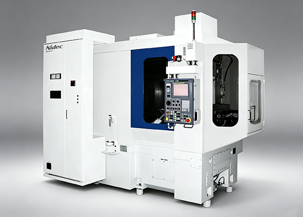
| Precision Gear Grinding Machine Spindles: As seen in a case with our Mexican customer using our P2 grade Rotary Table Bearings, the extreme loads and precision requirements of gear grinding demand maximum bearing stiffness to prevent chatter and maintain profile accuracy. | Equipment with Flexible Mounting Surfaces: If a rotary axis is mounted to a thin sheet metal plate or a non-rigid frame, the mounting surface will deform under load. An infinitely stiff bearing cannot compensate for a weak foundation. |
Common Design Mistakes That Negate Bearing Rigidity
Achieving a truly rigid mechanical assembly requires more than just selecting a stiff bearing. It demands a holistic design approach. Avoiding these common mistakes is critical to ensuring the catalog-specified stiffness of your bearing is realized in the final product.
Mistake 1: Underestimating Housing and Shaft Stiffness
This is the most frequent oversight. A high-rigidity bearing mounted in a thin-walled, "egg-shell" housing will conform to the housing's deflection. The system's stiffness will be that of the housing, not the bearing.
- Solution: Use finite element analysis (FEA) to model your housing and shaft under expected loads. Ensure the deflection of these support structures is an order of magnitude less than the bearing's expected deflection. As a rule of thumb, housing wall thickness should be substantial, with reinforcing ribs near the bearing seat.
Mistake 2: Improper Mounting and Preload Application
Crossed roller bearings achieve their high stiffness through preload (negative internal clearance). Incorrect mounting practices can destroy this preload or distort the bearing's thin rings.
- Incorrect Bolt Torquing: An uneven or non-sequential bolt tightening pattern can warp the bearing ring, creating high and low spots in the raceway. This leads to inconsistent torque, reduced rigidity, and drastically shortened life.
- Out-of-Tolerance Fits: An excessively tight interference fit can compress the bearing ring, drastically increasing preload beyond the design limit. This causes high friction, heat generation, and premature failure. A loose fit allows the outer ring to move in the housing, eliminating rigidity.
- Solution: Always follow the manufacturer's recommended mounting procedure, including bolt tightening sequences and torque values. Ensure that the housing bore and shaft diameters are machined to the specified tolerances for the selected fit. At BY Bearings, we provide detailed mounting instructions and can offer OEM customization for special mounting holes to simplify integration.
Mistake 3: Ignoring Thermal Effects
Temperature changes can significantly alter preload. A system that is perfectly preloaded at room temperature may become too tight or too loose at its operating temperature, especially if the housing and bearing materials have different coefficients of thermal expansion.
- Solution: Analyze the system's thermal state during operation. Consider the heat generated by motors, drives, and the bearing itself. Our bearings use high-grade GCr15 (SAE 52100) steel with a stable martensitic structure, ensuring predictable thermal performance. For applications with large temperature swings, consult with our engineers to determine the optimal initial preload.
How We Engineer and Verify Bearing Rigidity
Delivering a bearing that provides predictable, reliable rigidity is not accidental. It is the result of a disciplined engineering and manufacturing process, controlled at every stage to ensure performance aligns with specifications.
Our entire manufacturing process operates under a strict Quality Control system compliant with ISO 9001:2015. This system governs everything from raw material intake to final inspection.
Foundation in Material and Heat Treatment
Rigidity starts with the material. We use only premium GCr15 bearing steel, with its chemical composition verified by spectrographic analysis upon arrival. After forging, the crucial step is heat treatment. Our automated heat treatment line ensures each component achieves the optimal microstructure and hardness (HRC 60-64). This stable martensitic structure is what resists deformation under heavy loads, forming the very basis of stiffness.

Precision Grinding and Geometric Accuracy
A bearing's stiffness comes from the precise contact geometry between the rollers and raceways. Any deviation in form distributes the load unevenly, reducing rigidity. Our CNC grinding workshop can achieve precision levels up to P2 class. This allows us to control critical geometric parameters with extreme accuracy. Most importantly, we maintain runout control to within 1.5 μm. This level of precision ensures that rollers are correctly loaded across their entire length, maximizing the contact area and delivering the high moment rigidity required in demanding Bearings for Machine Tools.
Buyer's Checklist for Specifying a High-Rigidity Bearing
Before issuing an RFQ, use this checklist to clarify your requirements. Having these answers will help your bearing partner provide a solution that meets your system-level goals, not just a catalog part number.
- Load Definition: What are the maximum and typical radial, axial, and tilting moment loads?
- Stiffness Budget: What is the maximum allowable angular or linear deflection at the point of interest (e.g., tool tip, sensor) under load?
- System Analysis: Have you performed a stiffness analysis (e.g., FEA) of the shaft, housing, and mounting components? Is the bearing potentially the most compliant component?
- Operating Environment: What is the operating temperature range? Are there significant thermal gradients?
- Rotational Requirements: What are the required speed, acceleration, and duty cycle? This will influence lubricant selection and preload considerations.
- Dimensional Constraints: What are the space limitations for the bearing's inner diameter, outer diameter, and width?
Sharing this information allows us to move beyond a simple part selection. We can recommend the optimal preload, lubrication, and sealing options, and even propose custom dimensions or features to ensure the bearing performs as an integrated part of your system.
If your application demands high rigidity and you need to ensure system-level performance, our engineering team can help analyze your design. Submit your specifications, and we can provide a detailed recommendation and get a quote.
 +8618939019135
 sales@bybearings.com
 +8618939019135