Bearings for Industrial Automation Reduce Joint Backlash
When a robot reaches the correct encoder position but the tool point settles inconsistently, the immediate question is whether the problem comes from the reducer, bearing support, mounting structure, or control settings. Bearings for Industrial Automation affect this result because radial and axial clearance at the joint support can turn into visible end effector movement, especially on long robotic arms or compact rotary axes.
For maintenance and mechanical engineers, the goal is not simply to add more preload. The practical goal is to identify the source of lost repeatability, correct the bearing and mounting condition, and avoid creating excess running torque or heat. BY Bearings supplies crossed roller bearings, harmonic drive bearings, crossed tapered roller bearings, rotary table bearings, slew bearings, thin section bearings, spherical roller bearings, cylindrical roller bearings, and thrust bearings for precision motion applications.
For robot wrists, compact joints, and direct drive axes, Bearings for Automation Industry applications often require a support arrangement that can carry combined radial, axial, and overturning loads while maintaining controlled internal clearance.

Separate the Symptom From the Suspected Cause
A repeatability complaint is an observation, not a confirmed bearing failure. Before adjusting a robot joint bearing preload, first identify when the movement appears and whether it changes with direction, payload, temperature, or joint angle.
Start with a simple comparison. Command the same joint position from opposite directions, then observe the output flange, tool point, or dial indicator reading after the servo settles. If the final position differs by direction, mechanical lost motion is possible. If the position varies without a directional pattern, control tuning, external cable forces, lubrication condition, encoder feedback, or a loose mounting interface may also be involved.
| Observed symptom | What it may indicate | Next action | Limit of the observation |
|---|---|---|---|
| Position shifts after reversing direction | Possible internal clearance, gear clearance, loose fasteners, or fit movement | Check the joint support and reducer mounting before changing preload | Directional shift alone does not prove the bearing is the source |
| Error increases with payload | Possible structural deflection, bearing clearance, or insufficient support stiffness | Compare unloaded and loaded readings at the same joint angle | Payload effects can also come from the arm structure or fixture |
| Joint becomes harder to rotate after adjustment | Possible excessive preload, distorted rings, or mounting interference | Stop adjustment and compare torque with the assembly specification | Higher torque is not proof of correct preload |
| Error rises as the joint warms up | Possible excessive preload, lubrication issue, thermal growth, or motor loading | Record temperature trend, torque trend, and position deviation together | Do not attribute thermal behavior to one component without records |
| Noise or rough motion at one angular position | Possible contamination, ring distortion, local damage, or mounting face error | Inspect mounting surfaces and stop operation if motion becomes abnormal | Controller oscillation can also create audible effects |
The most useful first record includes the robot model, joint number, reducer type, bearing part number, payload, direction of travel, temperature condition, and the measured position difference. This prevents a common mistake: replacing a bearing because of automation gearbox backlash that actually originates at a loose flange or housing interface.
Follow a Diagnosis Order Before Changing Preload
Use the least invasive checks first. A bearing preload adjustment should not be the first response when the equipment history is incomplete. The order below helps separate accessible installation faults from issues that require joint removal or supplier review.
Confirm the complaint under a repeatable test. Use the same payload, speed, direction reversal, joint angle, and dwell time. The conclusion is simple: if the symptom cannot be repeated, do not alter the mechanical stack. A changing test setup cannot support a meaningful preload decision.
Review recent mechanical changes. Check whether the reducer, motor, flange, arm section, cable routing, lubricating procedure, or mounting bolts were recently changed. A new condition following service points first to the serviced interface. This check does not identify the exact fault, but it narrows the inspection area.
Check accessible fasteners and mating faces. Look for uneven bolt seating, witness marks around the bearing seat, flange gaps, damaged locating shoulders, or debris between clamped faces. Any visible seating issue should be corrected before evaluating internal bearing condition. Do not tighten beyond the assembly drawing or equipment manufacturer instruction.
Measure directional movement at the output. With the drive safely disabled according to site procedures, apply a controlled manual reversal and measure output movement if suitable equipment is available. Movement at the output may come from the reducer, bearing, or joint interfaces. Compare observations at several angular positions.
Check running behavior. Rotate through the available travel range and note whether resistance is uniform, whether torque rises after warm up, or whether one area feels different. Uniform resistance does not confirm correct preload, but localized resistance supports further inspection of mounting geometry, contamination, or damage.
Escalate before internal disassembly when evidence is mixed. If the robot has abnormal noise, rapidly rising temperature, binding, or unclear movement paths, stop adjustment and obtain engineering support. Internal intervention without the bearing arrangement drawing can create more error than it removes.
This procedure fits commissioned equipment where positioning drift is present but the root cause is uncertain. It does not replace the robot manufacturer’s safety process, torque instructions, or reducer service procedure.
How Preload Mounting Stiffness and Fit Tolerances Work Together
Preload, mounting stiffness, and fit tolerances must be treated as one system. A correctly selected crossed roller bearing can still lose repeatability if the housing flexes, the shaft shoulder is not square, or the fit allows ring creep. Conversely, increasing preload to compensate for a weak or distorted mounting structure can raise torque and heat without solving the original movement.
The correct conclusion is this: use the bearing preload specified for the bearing arrangement, make the mounting stack stiff and accurately seated, and verify fits against the bearing drawing. This approach fits robot joints and rotary axes where compact size and high overturning stiffness are required. It does not apply as a universal adjustment method because bearing design, reducer structure, lubrication, speed, and load cycle must all be considered.
| Factor | How it prevents repeatability loss | What to inspect | Risk when overcorrected |
|---|---|---|---|
| Preload | Reduces internal movement between rolling elements and raceways under reversing load | Specified preload class, assembly orientation, adjustment method, and measured running behavior | Excess torque, heat, wear, and reduced motion efficiency |
| Mounting stiffness | Limits ring tilt and housing deflection under payload and overturning moment | Housing wall stiffness, flange contact, bolt seating, support shoulder, and arm interface | Thicker or tighter parts alone may not fix distortion caused by poor face geometry |
| Fit tolerances | Stops unintended movement between the ring and its seat while allowing the intended assembly condition | Shaft and housing dimensions, roundness, seating length, shoulder condition, and drawing requirements | An interference condition outside the design intent can distort a precision ring |
| Mounting face accuracy | Keeps the bearing rings supported evenly during clamping | Burrs, paint, dents, contamination, uneven contact, and bolt tightening sequence | Higher bolt load cannot correct an uneven or damaged contact face |
A practical example is a compact wrist joint with a crossed roller bearing supporting a harmonic drive output. If reversal error becomes visible only when the tool is extended, inspect the mounting stiffness and output flange first. The added moment load may be tilting the bearing rings through a flexible support path. If the assembly is then tightened by adding preload alone, the joint may feel firmer at rest but develop higher torque during operation.
For a crossed roller bearing preload arrangement, the bearing must be mounted according to the applicable drawing and sequence. Engineers should confirm whether preload is built into the bearing, set through an adjustment stack, or controlled through matched components. Do not mix rings, spacers, or rolling elements from separate assemblies unless the product documentation explicitly permits it.
Choose the Bearing Arrangement That Matches the Load Path
Bearings should be selected around the actual joint load path rather than the outside diameter alone. Robot joints commonly see reversing torque, radial load, axial load, and an overturning moment at the same time. A bearing type that is acceptable for simple radial rotation may not provide the stiffness needed at a tool-carrying joint.
Crossed roller bearings: A strong option for compact robot joints, rotary axes, and precision motion supports that carry combined loads. Their crossed roller arrangement can provide high rigidity in a compact envelope. Use them where joint tilt and directional repeatability are major concerns. They are not a substitute for a stiff housing or a correct mounting fit.
Harmonic drive bearings: Suitable when the bearing is integrated around a strain wave reducer arrangement. Use a bearing configuration intended for the reducer geometry and applied moment load. Do not assume every reducer issue is internal gear clearance; inspect the output support and mounting stack as well.
Crossed tapered roller bearings: Consider these where combined load capacity and rotary stiffness are required in a suitable mechanical layout. Review available space, mounting method, and adjustment process before selection. A design that needs controlled adjustment may not fit a maintenance plan requiring rapid field replacement.
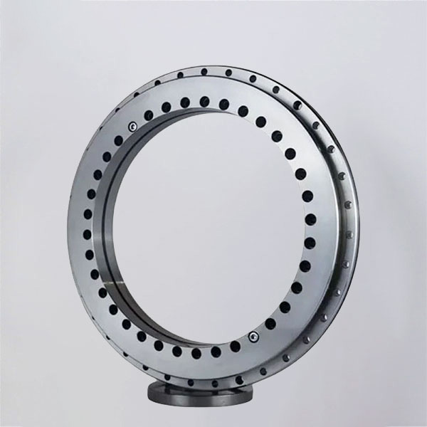
Rotary table bearings: Useful for indexed axes, turntables, and automation stations with combined loads and accuracy requirements. BY Bearings offers BRTM Series Rotary Table Bearings for precision rotary support applications. Verify axis load, speed, mounting structure, and required runout before selection.
Thin section bearings: Appropriate where radial space is limited and the load condition is suitable. See Thin Section Bearings when compact packaging is the driving requirement. Avoid selecting a thin bearing solely to reduce size when the joint has substantial overturning loads.
A recurring robotic arm positioning error should be evaluated at the tool point and at the joint output separately. If the joint output stays stable while the tool point moves, the arm, fixture, reducer, or tooling may be the larger contributor. If movement is measurable at the joint output and follows reversal direction, the bearing support, reducer connection, and mounting interfaces deserve closer review.
Correct Common Preload and Mounting Mistakes
Several field practices create avoidable problems. Each one can make a robot feel tighter during a brief hand check while reducing operating stability later.
Increasing preload without measuring the original symptom: The conclusion should be to record directional error before and after any approved adjustment. Without a baseline, there is no evidence that the adjustment improved repeatability. This is unsuitable when the assembly has no documented preload adjustment method.
Using preload to compensate for a flexible bracket: Reinforce or correct the support path first when deflection rises with payload. Preload controls internal bearing movement; it cannot remove bending from a weak arm flange or housing. This distinction matters most in long-reach arms and offset tooling.
Ignoring mounting face contamination: Clean and inspect all contact surfaces before assembly. A small burr, chip, coating buildup, or dent can tilt a ring and create uneven running behavior. Cleaning alone will not resolve damage within the reducer or bearing.
Assuming directional error is only gearbox clearance: Check output flange movement, bearing seat condition, and coupling interfaces before assigning the cause. This is the first practical step in understanding how to reduce backlash in robot joints without unnecessary component replacement.
Judging preload by hand force only: Follow the bearing and machine assembly specification, then verify the original repeatability test and operating behavior. Hand feel is subjective and is not sufficient for high-precision equipment.
Ignoring heat after adjustment: Compare the temperature trend and running condition under the same duty cycle used before service. If torque or temperature behavior worsens, stop and reassess the preload, fit, lubrication, and mounting geometry.
Verify the Repair and Know When to Escalate
After a documented correction, repeat the same direction reversal test, payload condition, joint angle, speed, and dwell time used during the initial diagnosis. The repair is supported when the original observed movement is reduced and the joint does not show abnormal torque, noise, or temperature behavior during the intended duty cycle.
If the result improves at one joint angle but not another, do not call the issue resolved. Angle-specific behavior may indicate local ring distortion, contamination, a mounting face issue, or a separate reducer condition. Send the test record, bearing identification, photographs of the mounting surfaces, assembly drawing details, and before-and-after observations to the equipment engineering team or bearing supplier.
BY Bearings has more than 15 years of precision bearing manufacturing experience and supports OEM and ODM customization for special dimensions and mounting requirements. Its precision bearing production includes P5, P4, and P2 classes, with runout controlled within 1.5 μm and 100% inspection before shipment. These controls support component quality verification, but final robot repeatability still depends on correct joint design, mounting condition, reducer integration, and commissioning procedure.
For example, BY Bearings supplied P2 rotary table bearings for gear grinding equipment in Mexico. That application demonstrates experience with precision rotary support requirements; it does not mean that a rotary table bearing is automatically the right replacement for every robot joint. For joint and compact-axis applications, Precision Crossed Roller Bearings should be assessed against the actual load path, installation space, preload approach, and interface geometry.
Submit your joint drawing, load condition, and repeatability test record to get a quote or request bearing selection advice from BY Bearings.
 +8618939019135
 sales@bybearings.com
 +8618939019135