
Bearings for Robotics: How Joint Layout Changes Choice
Start with the joint load path, not the bearing catalog
How a robot joint is arranged changes where radial force, axial force, overturning moment, and drive torque enter the bearing. That is why Bearings for Robotics should be shortlisted from the joint layout first, before comparing outside diameter, bore size, or nominal accuracy class.
A compact six-axis arm, a hollow-wrist handling robot, and a parallel-link pick-and-place machine may all rotate around an axis. Their bearing requirements are still different. One joint may place a long cantilevered arm directly on the bearing. Another may pass cables, air lines, and a drive shaft through the center. A third may use two links that share the load through separated support points.
For early-stage robot design, the practical question is: which bearing architecture carries the actual load path with the fewest added parts and the most controllable stiffness? For many articulated axes, Bearings for Industrial Robotics are selected around crossed roller or harmonic-drive bearing architectures because they can manage radial, axial, and moment loads in a compact package. However, that is not an automatic answer for every joint.
BY Bearings manufactures crossed roller bearings, harmonic drive bearings, crossed tapered roller bearings, rotary table bearings, slew bearings, thin section bearings, cylindrical roller bearings, spherical roller bearings, and thrust bearings. The appropriate choice depends on the geometry around the rotation axis, the support span available, the reducer arrangement, and the target positioning behavior.
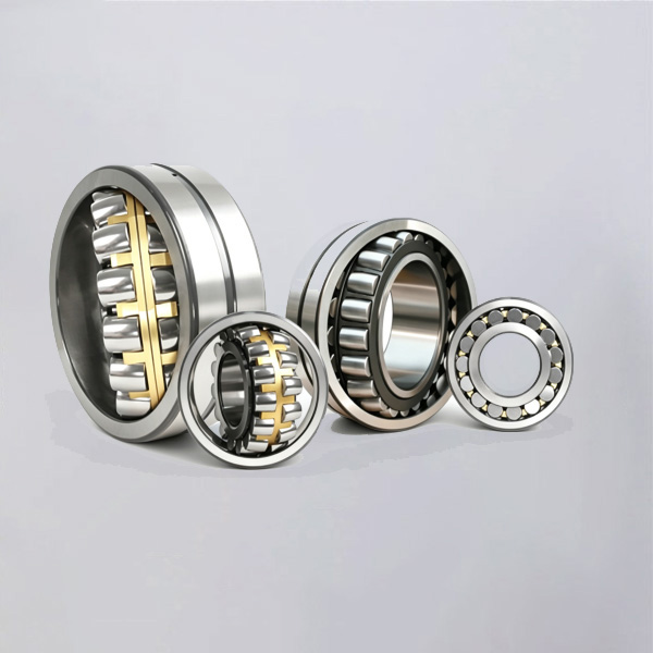
Match revolute, hollow-shaft, and parallel-link layouts to bearing architecture
The table below provides the first selection filter. It maps the joint arrangement to the dominant bearing loads and identifies bearing architectures that are usually worth evaluating. It is not a final catalog selection; bearing size, preload, mounting stiffness, duty cycle, and reducer behavior still need review.
| Joint layout | Typical load path | Suitable bearing architecture | Why it fits | When it may not fit |
|---|---|---|---|---|
| Revolute joint with cantilevered arm | Radial load plus axial load and a high overturning moment from the arm length and payload offset | Crossed roller bearing; crossed tapered roller bearing; rotary table bearing for heavier joint structures | These architectures can support combined loads around one axis and provide high tilting stiffness when mounted against rigid housings. | A compact bearing will not compensate for a flexible reducer flange, thin arm casting, or weak mounting bolts. |
| Hollow-shaft wrist or through-bore joint | Combined loads around a central opening; cable routing and drive components limit radial build space | Thin section bearing for space-led designs; crossed roller bearing with a suitable bore; harmonic drive bearing where reducer integration is required | The central bore keeps routing clear while the bearing arrangement supports rotation without adding a separate offset shaft. | Thin section bearings are not the preferred default when a large overturning moment must be carried in a very short axial span. |
| Parallel-link or dual-support joint | Loads shared through two links or two spaced supports; bearing reactions may be separated between sides | Paired radial and thrust bearing arrangements; crossed roller bearings at compact pivots; cylindrical roller and thrust bearing combinations where functions are separated | The mechanical structure can create useful support spacing, reducing the moment carried by one individual bearing. | Do not assume equal load sharing if link stiffness, machining position, or assembly preload differ between sides. |
| Large-base rotary joint | High radial force, axial force, and overturning moment from the upper structure; low-speed positioning may be required | Rotary table bearing; crossed tapered roller bearing; slew bearing for larger diameters and structural interfaces | A bearing designed for combined loading can simplify the base structure and support a large rotating assembly. | A slew bearing is not automatically the best answer where very fine positioning, low torque variation, or limited runout is the main requirement. |
Revolute joints: treat the arm as a lever
In a standard revolute shoulder, elbow, or wrist axis, the arm and payload act at a distance from the bearing centerline. The bearing therefore sees more than the payload weight. It also sees an overturning moment created by the offset. This moment often drives bearing choice before radial load does.
A crossed roller bearing is a strong candidate when one compact bearing must handle radial, axial, and moment loading. The rollers are arranged in alternating directions, allowing the bearing to react loads from multiple directions. This suits compact robot joints with limited axial space and a rigid housing. Review Precision Crossed Roller Bearings when the joint needs a single bearing architecture for combined loading.
The limit is structural. A high-precision bearing mounted in a compliant arm casting can still produce joint deflection. If the reducer output flange bends under load, the bearing raceways may not stay aligned as intended. In that case, increasing bearing precision alone may not improve end-effector repeatability.
Hollow-shaft joints: preserve the center opening without ignoring moment load
Hollow joints are common where motor cables, encoder wiring, pneumatic lines, or process hoses must pass through the axis. The opening is useful, but it removes space that might otherwise be used for a larger shaft or wider bearing support.
For a light wrist with modest external moment, a thin section bearing can preserve radial space and allow a large bore relative to the bearing cross-section. For a hollow joint that also carries an offset tool or a short but heavily loaded arm, evaluate a crossed roller architecture instead. It has a more direct route for reacting combined loads.
Where the reducer and bearing are selected as one functional unit, Bearings for Harmonic Drive applications require special attention to the reducer output interface. The bearing must support external joint loads while the reducer transmits torque. Check the flange geometry, bolt circle, available bearing seat, and whether the reducer housing is designed to serve as a stiff bearing support.
Parallel-link joints: use support spacing, but verify load sharing
Parallel-link layouts can reduce the moment imposed on a single pivot because forces are carried through multiple links and support points. This can permit smaller individual bearings than a single-sided cantilever arrangement. The benefit depends on matched geometry.
If one link is stiffer, one pivot axis is offset, or assembly clearances differ, load sharing becomes uneven. One bearing can become the primary load carrier while the other mainly follows the motion. For this reason, designers should not select two identical bearings simply because the mechanism looks symmetrical. Confirm pivot spacing, link stiffness, machining tolerances, and assembly method.

Understand which bearing parameters change robot behavior
Catalog parameters only become useful when connected to a joint-level consequence. The following relationships help design engineers decide what information belongs in an early bearing request.
| Parameter or design condition | What it affects in the robot joint | Selection consequence | Limit of the interpretation |
|---|---|---|---|
| Overturning moment | Angular deflection at the joint and tool-point movement at the end of the arm | Favor a bearing architecture that carries moment directly, plus a housing with sufficient stiffness. | Moment capacity alone does not predict system deflection; flange and casting compliance also matter. |
| Axial space | Whether a wide bearing pair can be used or a compact single-bearing solution is needed | Use crossed roller or integrated bearing arrangements when axial stack height is constrained. | A shorter stack can require a larger diameter or a stronger housing to manage moment. |
| Through-bore diameter | Cable, hose, shaft, and encoder routing through the joint center | Assess thin section or hollow-compatible crossed roller configurations early in the layout. | A larger bore reduces available bearing cross-section and may change stiffness requirements. |
| Preload or internal clearance | Backlash feel, vibration tendency, friction torque, and thermal sensitivity | Specify the desired operating condition together with temperature and load direction. | More preload is not always better; it can raise friction and heat. |
| Runout requirement | Axis wobble, encoder reference stability, and tool or camera position consistency | Specify radial and axial runout at the relevant mounting surfaces, not only a general precision class. | Installed runout also depends on housing seats, flange flatness, and assembly cleanliness. |
Preload is commonly misunderstood. A designer may request the highest possible preload to remove play. That can reduce perceptible looseness, but it may also increase friction torque and heat generation. It is appropriate when positioning stiffness is the first priority and the thermal path is controlled. It is less appropriate for a continuously rotating axis where low torque and temperature stability are more important.
Likewise, a high accuracy class is not a substitute for correct mounting. BY Bearings can provide grinding accuracy up to P2 class and controls runout within 1.5 μm, with 100% inspection before shipment. Those manufacturing controls are useful for precision joint projects, but the benefit can be lost if the housing bore is out of round, the mounting face has burrs, or clamping forces distort the rings.
Choose between a single combined-load bearing and separated bearing functions
Robot designers often face a packaging decision: use one bearing that handles several load directions, or use separate radial and thrust bearing functions. Neither route is universally better.
Select a single combined-load architecture when the joint needs short axial length, high tilting stiffness, and simplified assembly. Crossed roller bearings are often suitable for articulated axes and compact direct-drive modules. The trade-off is that housing and mounting-face accuracy become especially important because one bearing is carrying the full combined load condition.
Select separated radial and thrust functions when the mechanism has adequate support span and each load direction can be routed clearly through the structure. This may suit parallel-link joints or long shafts where radial support and axial location can be placed apart. The trade-off is more components, more assembly interfaces, and more opportunities for tolerance accumulation.
Select a rotary table architecture when a robot base or large axis needs a bearing designed around combined loading and high tilting stiffness. BRTM Series Rotary Table Bearings are relevant for layouts where the bearing supports a rotary structure rather than a narrow wrist joint. The limit is package size; a rotary table bearing may not fit compact arm axes.
Select a slew bearing when structural diameter is available and the rotating upper assembly creates high moment loading. Slew Bearings can suit larger rotational structures, but design teams should verify positioning, friction, and mounting requirements against the motion target.
The bearing must also match the reducer layout. If the reducer output is close to the bearing, the support can be compact but may concentrate load into a short structure. If the motor and reducer are offset, belt or gear forces can introduce additional radial loading that was not present in the first kinematic sketch. Add those transmission forces to the bearing load review rather than evaluating payload loads alone.
Use this early selection procedure before requesting drawings or specifications
A clear request reduces redesign cycles between robot engineering and bearing engineering. Use the following procedure before asking for a bearing recommendation.
Draw the rotation axis and fixed structure. Mark which ring rotates and which ring mounts to the stationary arm, bracket, or base.
Mark all load entry points. Include payload force, arm self-weight, process force, cable pull, belt tension, gear mesh force, and emergency-stop inertia where relevant.
Identify the offset from each load to the bearing centerline. This identifies where overturning moment is created. A small load at a long distance can be more important than a larger centered load.
Define the package restrictions. State maximum outside diameter, bore requirement, permitted axial height, flange arrangement, mounting holes, and whether wiring must pass through the center.
Set the motion priorities. Indicate whether the axis is mainly positioning, continuously rotating, oscillating, carrying a high payload, or operating at low speed where torque variation is noticeable.
Specify the accuracy target at the assembly level. Include allowable axial wobble, radial runout, angular deflection, and repeatability requirements where available. Do not provide only a general statement such as “high precision.”
Review mounting surfaces. Provide housing bore, shoulder, face, and clamping details. Bearing performance depends on the installed interface.
Check common selection mistakes before freezing the robot architecture
Choosing only by outside diameter: Two bearings with similar dimensions can have different load paths and mounting requirements. Compare the actual radial, axial, and moment condition.
Ignoring the arm’s lever effect: A wrist tool mounted away from the axis creates overturning moment even when the payload itself appears light.
Assuming a hollow joint is automatically a thin section bearing application: The through-bore requirement is only one factor. Tool offset and moment load may point to a crossed roller solution.
Requesting maximum preload without a thermal review: Higher preload can increase friction torque and heat. Match preload to positioning and duty requirements.
Specifying bearing precision without mounting tolerances: Ring runout cannot correct a distorted housing seat or uneven bolting surface.
Using identical bearings in a parallel-link layout without checking load sharing: Symmetrical appearance does not guarantee symmetrical reactions.
BY Bearings supports OEM and ODM customization, including special dimensions and mounting-hole requirements where the standard envelope does not match the robot architecture. For projects that need verified precision controls, our inspection process includes 100% pre-shipment inspection. A Mexico customer case involving P2 rotary table bearings for gear grinding also reflects the type of accuracy-focused requirement that benefits from early load-path and mounting review.
For robot developers, the best bearing choice is usually made before the arm casting, reducer flange, and cable-routing path are finalized. Submit your joint drawing, load directions, package limits, and motion requirements to get a quote or request selection advice from BY Bearings.
 +8618939019135
 sales@bybearings.com
 +8618939019135

