
Bearings for Robotics: Match Lubricants to Duty Cycles
Why one grease works in one robot joint and fails in another
Two robots can use the same crossed roller bearing size and still need different grease. The reason is the motion profile. A pick-and-place arm makes thousands of short, fast strokes per hour. A welding robot holds a pose, then moves in bursts near a heat source. A continuous-path robot rarely stops. Each profile loads the lubricant film differently.
This guide is for maintenance engineers and robot OEM teams who have already chosen the bearing type and now need to settle grease viscosity, fill quantity and relubrication interval. When you finish, you will have a written lubrication spec for each joint, a trial plan to confirm it, and a list of symptoms that tell you which step to revisit. For Bearings for Robotics, this matters because joints are small, sealed and expensive to open.
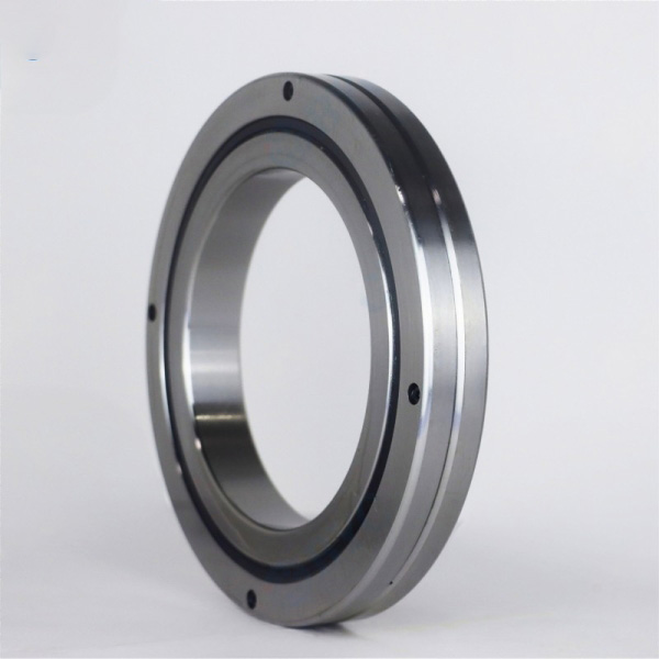
We write this from the bearing side. At BY Bearings, our team supplies Precision Crossed Roller Bearings, harmonic drive bearings and rotary table bearings for robotic and automation joints. The lubricant decision is usually where reliability is won or lost after the bearing is chosen.
Collect these inputs before you pick a grease
You do not need laboratory data. You do need six facts about each joint. Without them, any grease recommendation is a guess.
| Input | Where to get it | Blocks progress? |
|---|---|---|
| Speed profile (typical and peak rpm or deg/s) | Robot program, motion controller log | Yes |
| Stroke angle (full rotation vs. small oscillation) | Program waypoints | Yes |
| Dwell time under load (seconds to hours) | Cycle diagram, takt time | Yes |
| Operating temperature at the bearing | Surface thermocouple or IR reading after 1–2 hours of running | Yes |
| Environment (cleanroom, spatter, washdown, vacuum) | Site survey | Yes |
| Preload and load type (radial, axial, moment) | Bearing drawing, design calculation | No, can be refined later |
Temperature is the input most often missing. Design-stage estimates are usually too low because motor heat travels into the housing. Measure it on a running machine if you can. If you cannot, say so in the spec and plan a shorter first inspection interval.
How duty-cycle speed, dwell time and heat set viscosity, fill and relubrication interval
Three variables drive the lubricant decision. Speed controls how thick a film the base oil can build and how much heat the grease generates by churning. Dwell time controls whether the film survives at standstill and whether grease redistributes. Heat controls how fast the base oil thins and the grease oxidizes. The table turns those variables into starting choices. Treat the values as starting points to confirm against your grease datasheet and a trial run, not as fixed rules.
| Duty-cycle condition | Effect on lubricant | Viscosity direction | Fill direction | Relubrication direction |
|---|---|---|---|---|
| High speed, continuous rotation | Churning heat; grease thrown out of the contact | Lower base-oil viscosity, soft consistency (often NLGI 1–2) | Partial fill of free space to limit churning | Shorter, driven by temperature rise |
| Low speed, heavy moment load | Thin film risk; boundary lubrication | Higher base-oil viscosity, with EP additives if loads are high | Fuller fill to keep reserve at the contact | Longer if sealed and cool |
| Short oscillating strokes (small angle) | Grease is not redistributed; the same rolling elements stay in one zone | Medium viscosity, good mechanical stability | Fuller fill; ensure the grease can reach the track | Short; watch for fretting marks |
| Long dwell under load | Oil separation and film squeeze-out at standstill | Grease with low oil bleed | Moderate to full | Add a periodic movement through a wider stroke, not just more grease |
| High ambient or nearby heat source | Faster oxidation and oil loss | Higher thermal-rated base oil and thickener | Avoid overfilling, since heat expands the grease | Shorter; set by grease life at your measured temperature |
Two limits apply. First, overfilling is not a safe default. In a high-speed joint it raises temperature and torque. Second, a stiffer grease is not always better. In low-torque robot joints it increases friction torque and can disturb positioning repeatability. Match the grease to the joint's torque budget.
Worked examples: pick-and-place, welding and continuous-path robots
These are scenarios, not customer test results. They show how the logic above changes the answer.
Pick-and-place arm
Short strokes, high acceleration, frequent reversals. The bearing seldom completes a full turn, so grease stays in the same part of the track. Choose a medium-viscosity, mechanically stable grease and fill the bearing more fully so reserve is available at the working zone. Plan an early relubrication check, then extend it only if the removed grease still looks smooth and the torque is stable. The most common mistake is picking a very light grease for speed, then seeing fretting at the stroke end points.
Welding robot wrist and arm joints
Heat and contamination dominate. Dwell under load is frequent during positioning, and radiant heat from the process raises bearing temperature. Pick a grease rated well above your measured bearing temperature, with low oil bleed. Check seals first, since spatter and dust shorten life faster than a small viscosity error. Do not extend intervals because the joint "sounds fine"; heat-aged grease can still run quietly until the film breaks down.
Continuous-path robot (sealing, dispensing, machining)
Long periods at steady speed, little standstill. Churning heat is the main risk. Use a lower base-oil viscosity, a partial fill, and set the interval by temperature rise rather than by calendar. If the bearing runs hotter than the surrounding structure after the first hour, reduce fill before changing grease type.
Step-by-step: build and verify the lubrication spec for each joint
- Classify the duty cycle. Label each joint as full-rotation, small-oscillation or mixed. Success looks like one label per joint. A joint with two labels needs the more demanding case as the design basis.
- Record peak temperature. Measure at the housing next to the bearing after the machine reaches steady state. Mistake to avoid: reading the outer cover instead of the bearing seat.
- Choose viscosity direction and consistency. Use the table above as a filter, then shortlist two greases whose datasheets cover your temperature, speed and load range.
- Set fill. Pack the bearing and fill only the free space your design allows. Write the quantity in grams or cm³, not "until full", so a technician can repeat it.
- Run a short-interval trial. Inspect after a short first interval, compare grease condition and measure friction torque or motor current against the baseline.
- Extend only with evidence. If temperature, torque and grease appearance are stable, lengthen the interval in small steps. Record each change.
Completion check and recovery
You are done when three things hold: bearing temperature stabilizes at or below your measured baseline, friction torque or motor current stays within your baseline band, and removed grease shows no discoloration, metallic particles or hardening. If one fails, revisit the matching step.
| Symptom | Likely cause | Revisit |
|---|---|---|
| Temperature climbs after relubrication | Overfill or viscosity too high | Step 4, then step 3 |
| Fretting marks at stroke end points | Small-angle oscillation with insufficient redistribution | Step 1 and 3 |
| Dark, hardened grease | Operating temperature above grease rating | Step 2 |
| Rising torque or positioning drift | Contamination or degraded grease | Seals, then step 5 |
Lubrication cannot compensate for a bearing that is out of tolerance. That is why our Quality Control process includes 100% inspection before shipment, with runout controlled within 1.5 μm. Stable runout makes torque and temperature readings in your trial easier to interpret. We have supplied crossed roller bearings for semiconductor equipment in Germany and P2 rotary table bearings for gear grinding in Mexico; in both applications, low vibration and stable torque depend on a consistent lubricant film as much as on the bearing grade.
Variations that change the procedure
- Harmonic drive joints. The bearing shares lubricant with the gear set, so confirm the grease is compatible with the strain wave gear before specifying it. See our Bearings for Harmonic Drive page for typical configurations.
- Preloaded crossed roller bearings. Negative clearance raises friction, so avoid stiff greases and heavy fills unless the torque budget allows it.
- Cleanroom or vacuum equipment. Outgassing and particle limits override the viscosity table. Use a grease approved for the environment and stay with minimal fill.
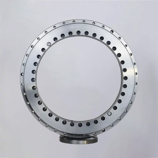
- Rotary tables on robot positioners. Large diameters with long dwell and moment loads favor higher viscosity and fuller fill. Our Rotary Table Bearings range covers these axes.
Next step
If you send us the joint type, speed profile, dwell time and measured temperature, we can review the bearing and suggest a lubrication starting point. We can also supply OEM-customized dimensions, and our products carry a 12-month warranty from shipment. To discuss your application or get a quote, share your drawings and duty-cycle data with our team.
 +8618939019135
 sales@bybearings.com
 +8618939019135

