
Control Thermal Runout in High-Precision Crossed Rollers
Why Runout Reads Fine Cold and Drifts After 30 Minutes of Running
You mount the bearing, indicate the rotating face, and the number looks excellent. Then the axis runs for half an hour and the same indicator shows a different story. If that sounds familiar, the bearing is rarely the cause. The mounting system around it is changing shape as it heats up.
This guide is for mechanical engineers who set assembly requirements for precision stages, inspection equipment and rotary tables. By the end you will have a repeatable workflow for High Precision Crossed Roller Bearings: pick the right housing and fit, set preload, warm the axis up in stages, and confirm that runout stays inside your limit at operating temperature, not only on the bench.
Starting state: the bearing is selected, the housing and shaft are machined, and you can measure the axis with a dial indicator or a non-contact probe. What follows is the installation and commissioning sequence that most catalogues leave out.
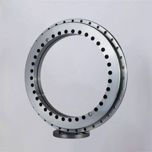
What You Need Before Mounting
Some inputs block progress. Others can be settled later. Sort them before you touch the bearing.
| Input | Why it matters | Blocks start? |
|---|---|---|
| Housing and shaft material | Sets how the fit changes with temperature | Yes |
| Bearing drawing with bore, outer diameter and tolerance data | Fit values must come from the drawing, not from memory | Yes |
| Required runout limit at operating temperature | Defines pass/fail for the final check | Yes |
| Expected operating speed range and duty cycle | Drives the warm-up plan | Yes |
| Heat sources nearby (motor, drive, spindle) | Predicts uneven housing growth | No, but log it early |
| Dial indicator or probe, torque wrench, thermocouple or IR thermometer | Needed for every checkpoint below | Yes |
| Lubricant choice | Affects friction heat during run-in | No, confirm before warm-up |
One limit worth stating: if your requirement is a runout figure at room temperature only, you can skip the thermal steps. As soon as the axis runs continuously or sits beside a motor, they apply.
Housing Material, Shaft Fits and Warm-Up: How Each Prevents Thermal Runout
Thermal runout control comes down to three decisions. Housing material decides how much the bore grows. The shaft and housing fits decide whether that growth shifts the ring. The warm-up routine decides whether you find the shift before the machine goes into production.
Housing material
Steel housing. Expansion is close to that of GCr15 bearing steel, so the outer-ring fit stays nearly constant as temperature rises. Choose it when the axis runs hot or the runout budget is tight. The trade-off is weight.
Aluminum housing. Light and easy to machine, but the bore grows faster than the steel outer ring. A fit that is snug at 20 °C can loosen when warm, letting the ring shift and change runout. It works for light-duty, low-heat axes. It does not suit long continuous duty beside a motor unless you verify the fit hot.
Cast iron housing. Stable and damping, with expansion close to steel. A good compromise where weight is not critical.
Shaft and housing fits
The right crossed roller bearing mounting fit depends on which ring rotates. As a general rule, the rotating ring takes the tighter fit and the stationary ring the looser one. Take exact tolerance classes from the bearing drawing, or send us your drawing and we will check them against your layout. Two points matter for thermal behavior:
Do not tighten a fit to "make up" for an aluminum housing. Added interference raises ring distortion and preload, which raises friction and heat.
Keep the stationary ring free enough to follow small thermal growth without binding. A ring that cannot move builds stress, and the stress shows up as periodic runout.
Warm-up procedure
Start at low speed with no process load.
Step the speed up in stages, logging housing temperature and runout at each stage.
Hold each stage until two readings taken a fixed interval apart (for example, 10 minutes) agree.
Record the final stable temperature. That is the condition your runout limit must be met at.
| Decision | Safer choice for thermal stability | Does not apply when |
|---|---|---|
| Housing material | Steel or cast iron | Weight limit forces aluminum; then verify the fit hot |
| Stationary ring fit | Slightly free per drawing | The design needs a locked ring for stiffness; then confirm preload hot |
| Warm-up | Staged, logged, to equilibrium | The axis only runs in short, cool bursts |
Mounting and Preload Setup: Step by Step
Preload on a crossed roller bearing comes from negative clearance in the design. Your job is to avoid adding distortion on top of it. Follow this order.
Inspect the mounting faces. Check flatness and squareness of the shoulders and the seat. Checkpoint: the bearing seats with no visible light gap and no rocking. Common mistake: burrs or paint on the shoulder, which tilts the ring and shows up as once-per-revolution face runout.
Clean and lightly lubricate the seats. This lets the ring seat evenly and prevents fretting later.
Seat the bearing square. Press or draw it in evenly, never by hammering on one side. Checkpoint: rotate by hand and feel for uniform torque with no notchy spots.
Fit the clamping ring or flange. Tighten bolts in a cross pattern, in at least two torque stages, to the value on your drawing. Checkpoint: re-measure hand-turn torque after each stage. If torque climbs sharply, the housing is distorting the ring. Loosen and look at flatness before going on.
Confirm the preload feel. A correctly set crossed roller bearing preload setup gives smooth, even torque and no perceptible wobble when you push the table sideways. Too little preload shows up as play. Too much shows up as rising torque and heat after a few minutes.
Take the cold runout baseline. Measure radial and face runout at several angular positions and record them with room temperature.
Run the staged warm-up described above and repeat the measurement at each stable stage.
Bolt tightening sequence is the step people rush. It also causes the most mounting-induced runout we see in customer questions.
How to Reduce Rotary Axis Runout When the Numbers Do Not Hold
Asking how to reduce rotary axis runout only helps once you know which source you are fighting. Match the symptom to a step.
| Symptom | Likely cause | Revisit |
|---|---|---|
| Runout good cold, worse once warm | Housing growth loosening or loading the fit | Housing material and fit review |
| Runout repeats once per revolution and does not change with heat | Tilted seat, burr or uneven shoulder | Step 1, mounting face inspection |
| Runout shifts after bolt tightening | Housing flatness or uneven torque | Step 4, staged cross-pattern tightening |
| Torque and temperature keep rising | Excess preload or tight fit | Steps 4 and 5 |
| Wobble under sideways push | Insufficient preload or loose ring | Step 5, fit and clamping |
Completion check: the job is finished when runout stays within your limit at the stable operating temperature, torque is steady between two readings, and the baseline repeats after a cool-down. Passing only the cold measurement is not completion.
Bearing quality sets the floor for all of this. At BY Bearings, 100% inspection before shipment and runout control within 1.5 μm on our precision grades give you a known starting point, so any drift you see points to the installation, not an unknown. You can read how we check parts on our Quality Control page. We supplied crossed roller bearings to a German semiconductor equipment customer, a field where thermal stability matters. We also supplied P2 rotary table bearings to a Mexican customer for gear grinding. Both applications depend on the same fit, preload and warm-up discipline described here, and these steps apply equally to high precision crossed roller bearings in smaller stages.
Variations That Change the Procedure
Not every axis follows the same workflow. These cases alter the steps.
Compact stages and robot joints. The BRE Series Crossed Roller Bearings and similar slim sections have little housing mass to absorb heat, so run the warm-up with the actual drive installed. See our notes for Bearings for Industrial Robotics.
Machine tool rotary tables. Cutting loads add overturning moment on top of thermal effects. For heavy tilting loads, compare Rotary Table Bearings and crossed tapered designs, and repeat the check under load. Our Bearings for Machine Tools page covers typical setups.
Special dimensions or mounting holes. With OEM customization we can match your housing layout so the fit and clamping design suit your material choice from the start.
If you are unsure which fit, preload level or series suits your housing material, send your drawing and operating conditions. Our engineers will review them and recommend a configuration. You can get a quote or request selection advice through the same form.
 +8618939019135
 sales@bybearings.com
 +8618939019135

