
Crossed Roller Bearings: Cage vs Full-Roller Motion
Choose the Internal Roller Arrangement Before Finalizing the Bearing Specification
After selecting the bearing format, design engineers still need to answer a more specific question: should the rolling elements be retained by a cage, or should the bearing use a full-roller arrangement? The answer affects motion quality, friction torque, speed suitability, grease behavior, and usable load capacity.
Precision Crossed Roller Bearings use cylindrical rollers arranged alternately at right angles. This geometry lets one bearing support radial load, axial load in both directions, and overturning moment. However, the internal roller-retention method determines how those rollers move under preload, acceleration, load reversal, and temperature change.
A caged crossed roller bearing places a separator or cage between rollers to control spacing. A full roller crossed bearing uses a higher roller count with no cage separating adjacent rollers. Neither design is automatically better. The correct choice depends on whether the application places greater value on low and consistent torque, higher rotational speed, lubricant circulation, maximum load capacity, or compact stiffness.
BY Bearings supplies crossed roller bearings, harmonic drive bearings, crossed tapered roller bearings, rotary table bearings, slew bearings, thin section bearings, spherical roller bearings, cylindrical roller bearings, and thrust bearings for equipment builders. For precision applications, we support OEM and ODM customization, including bearing dimensions, mounting features, and application-specific requirements.
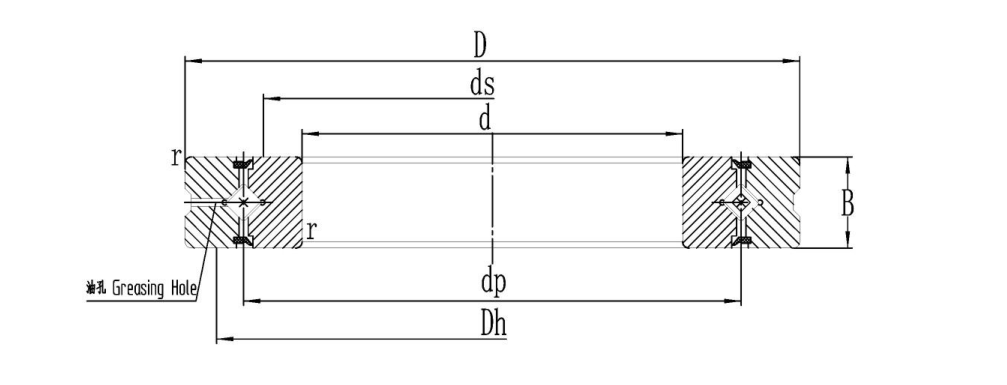
How Cage-Guided and Full-Roller Designs Change Operating Behavior
The main boundary is simple: select a cage-guided design when controlled roller spacing and smoother motion are the priority; consider a full-roller construction when the design needs the highest possible roller population within a given envelope and can accept stricter control of speed, lubrication, and thermal conditions.
| Parameter | Cage-Guided Roller Design | Full-Roller Design | What the Difference Means in Practice |
|---|---|---|---|
| Roller spacing | A cage or separator maintains defined spacing between rollers. | Adjacent rollers operate with no cage between them. | Cage guidance reduces roller-to-roller interaction. Full-roller arrangements require closer attention to contact conditions between rolling elements. |
| Friction torque | Often better suited to low, controlled, repeatable torque requirements. | May produce more friction variation as adjacent rollers interact, particularly when speed, preload, or lubricant condition changes. | For sensitive indexing, scanning, or direct-drive positioning, torque consistency can matter more than nominal load capacity. |
| Speed suitability | Generally the preferred direction when speed and smooth roller guidance are important. | More appropriate for slower rotation or oscillation where increased roller quantity is valuable. | Do not select a full-roller arrangement for speed simply because it has more rollers. |
| Lubrication behavior | Spaces created by roller separation can assist grease distribution through the bearing. | Higher roller density leaves less free internal space and places greater demand on lubricant selection and replenishment planning. | Lubrication must be reviewed with speed, mounting orientation, duty cycle, and contamination exposure. |
| Load capacity | Has fewer rollers because cage space is required. | Can provide more rolling elements in the same bearing envelope. | A full-roller layout may be suitable when static or slow-moving load demand is dominant, subject to the manufacturer’s rated load data. |
| Motion quality | Better suited to applications seeking smooth, controlled rotation and low vibration. | Can suit high-load, lower-speed duties but needs validation where torque ripple or micro-motion affects the process. | Prototype testing is still needed for high-accuracy systems. |
Recommendation: Start with a cage-guided arrangement when the axis is servo-driven, repeatedly indexed, or measured for low-speed rotational smoothness. The cage separates rollers and reduces direct roller interaction. This fits robotics joints, medical equipment, semiconductor handling stages, and direct-drive rotary systems. It may not be the best fit when available bearing space is fixed and the primary design constraint is maximum load capacity at slow speed.
Recommendation: Consider a full-roller arrangement when heavy combined load and tilting moment govern the design, while rotational speed remains limited and the lubrication plan is clearly defined. The higher roller count can use the available raceway length more fully. It does not remove the need to verify friction torque, heat generation, preload, and installation accuracy.
Torque Is Not Determined by Cage Type Alone
A frequent selection error is assuming that a cage always creates higher torque because it adds a component, or that a full-roller design always has lower torque because there is no cage. Both assumptions overlook how friction is generated.
Rolling resistance comes from several interacting sources: roller-to-raceway contact, roller-end guidance, seal drag where applicable, lubricant shear, preload, mounting distortion, and internal contact between adjacent rollers. The crossed roller bearing cage design influences several of these factors, but it is not the only variable.
Why cage-guided bearings are often selected for torque consistency
- Clear conclusion: A cage-guided design is normally the safer starting point for low-torque motion requirements.
- Reason: Roller separation helps avoid direct roller-to-roller contact and supports orderly roller circulation.
- Suitable scenario: A DD motor turntable that moves slowly, stops precisely, and reverses direction frequently.
- Limit: A cage cannot compensate for excessive preload, poor mounting-seat geometry, unsuitable grease, or housing distortion.
Why full-roller designs require system-level torque evaluation
- Clear conclusion: Full-roller designs should be evaluated under actual operating preload and lubricant conditions rather than selected from capacity alone.
- Reason: A higher roller population can increase internal interaction and alter how lubricant is sheared and redistributed.
- Suitable scenario: A heavily loaded rotary axis operating at modest speed where stiffness and available mounting space outweigh torque sensitivity.
- Limit: This approach may not suit inspection equipment or precision positioning axes where small torque changes affect encoder feedback, settling time, or surface quality.
When reviewing roller separator bearing torque, request the bearing supplier’s test condition rather than comparing isolated torque values. Torque data only becomes meaningful when preload, lubricant type, rotational direction, speed, temperature, and mounting method are identified. A torque value obtained under a light test condition cannot be treated as the expected value after installation in a heavily preloaded production assembly.
For rotary machining axes, the bearing should also be evaluated with the driven structure attached. A rotary table, chuck, fixture, or workpiece can introduce moment loading that changes raceway contact distribution. Where the application is a machine-tool rotary axis, review suitable Rotary Table Bearings alongside the crossed-roller option before committing to the internal configuration.
Speed, Lubrication, and Heat Must Be Evaluated Together
Crossed roller bearing lubrication is not a separate maintenance detail. It is part of the bearing selection. As rotational speed rises, lubricant churning and shear can increase friction and heat. As roller density rises, available internal space for lubricant movement can decrease. These effects are why a full-roller layout should not be treated as a universal upgrade.
A cage-guided design generally gives grease more defined pathways through the rolling-element set. That can support lubricant distribution during repeated rotation. A full-roller structure may require more deliberate review of grease type, fill quantity, relubrication access, and operating orientation because roller packing changes the internal free space.
| Operating Condition | Preferred Starting Direction | Reasoning | What Must Still Be Verified |
|---|---|---|---|
| Continuous rotation with frequent acceleration | Cage-guided rollers | Controlled spacing is generally better aligned with smooth roller circulation and stable motion. | Actual speed, preload, grease selection, motor torque margin, and temperature rise. |
| Slow oscillation under high moment load | Full-roller arrangement may be considered | Higher roller density may support greater load capability in the available bearing envelope. | Lubricant film condition, torque variation, false brinelling risk, and load distribution. |
| Precision indexing with short moves | Cage-guided rollers | Motion regularity and torque repeatability usually have greater value than maximum roller count. | Preload, runout, mounting flatness, and drive-controller tuning. |
| Heavy machine-tool cutting load | Evaluate both with full system data | Capacity alone is insufficient because stiffness, runout, speed, and thermal response all affect finished-part quality. | Combined radial, axial, and overturning loads plus duty cycle. |
For applications with short angular movement rather than continuous rotation, do not assume lubricant behavior is easier. Repeated oscillation can limit grease redistribution, especially when the axis stays within a narrow angle. In that case, ask the supplier to review the movement pattern and mounting orientation. This is particularly relevant for harmonic drive joints and robotic wrists. BY Bearings also offers bearing options for Bearings for Harmonic Drive assemblies where compact packaging and repeat positioning are both important.
Use Load Capacity Correctly: More Rollers Do Not Solve Every Stiffness Problem
A full-roller construction can place more rollers around the raceway, which may increase the available load-carrying capability for a given bearing size. That benefit is real in suitable conditions. Yet designers should avoid equating roller count directly with axis stiffness or accuracy.
System stiffness depends on bearing geometry, preload, raceway contact, mounting support, shaft and housing stiffness, bolt pattern, and applied moment. A bearing with a higher roller count can still underperform if the mounting faces are distorted or if preload is not controlled correctly.
Practical decision rule: choose a full-roller design only after confirming that load capacity is the actual constraint. If the axis instead suffers from chatter, settling error, uneven torque, or thermal drift, investigate preload, mounting rigidity, drive behavior, and lubricant selection before increasing roller density.
This distinction is important in CNC rotary equipment. BY Bearings has supplied P2 rotary table bearings for gear grinding in Mexico. That case supports the need to align bearing precision with the machine process, rather than treating load rating as the only selection factor. For demanding rotary-axis work, our BRTM Series Rotary Table Bearings can be reviewed where the machine requires a purpose-built rotary table bearing format rather than a general crossed-roller configuration.
Our precision manufacturing controls also support applications where rotational accuracy must be verified, not assumed. BY Bearings uses high-grade GCr15 bearing steel verified through spectrographic analysis, conducts metallographic examination after heat treatment, and performs 100% inspection before shipment. For applicable precision products, runout control is maintained within 1.5 μm. Engineers should still state their own required accuracy, preload, torque, and mounting conditions in the RFQ so that inspection criteria can match the application.
Common Specification Mistakes and How to Avoid Them
- Mistake: Selecting full rollers solely for higher load capacity.
Use a full-roller arrangement only when the load case and available envelope support that decision. If motion smoothness or speed is the main concern, begin with a cage-guided option. - Mistake: Comparing torque values without test conditions.
Request the preload, lubricant, speed, direction, and measurement method behind each value. Otherwise, the comparison does not support a design decision. - Mistake: Treating preload as a fixed catalogue feature.
Preload interacts with torque, heat, rigidity, and mounting tolerance. Specify the required motion and load behavior, then confirm an appropriate preload class with the supplier. - Mistake: Ignoring the duty cycle.
Continuous rotation, short indexing, repeated reversing, and narrow-angle oscillation create different lubrication and thermal conditions. Provide the actual motion profile. - Mistake: Omitting mounting details from the bearing inquiry.
Include shaft and housing material, fit concept, mounting-face geometry, clamping method, and axial retention method. The bearing cannot be evaluated independently from its support structure. - Mistake: Assuming a precision class alone guarantees machine accuracy.
Precision level matters, but total axis error also includes runout of mating parts, assembly cleanliness, mounting distortion, and drive-system behavior.
Prototype Testing Procedure for Cage and Full-Roller Options
The most reliable method is to test two technically valid configurations under the same machine conditions. A comparison should focus on the axis result, not only on individual bearing data.
- Define the motion: document continuous rotation, indexing angle, reversal frequency, dwell time, and target speed range.
- List all applied loads: include radial force, axial force in both directions, overturning moment, deadweight, cutting force, and load position relative to the bearing center.
- Set accuracy targets: identify allowable runout, positioning repeatability, vibration sensitivity, and torque consistency requirements.
- Specify mounting conditions: provide shaft and housing drawings, clamping arrangement, interface flatness requirements, and available lubrication access.
- Request comparable samples: keep bearing size, accuracy requirement, preload target, lubricant condition, and test assembly as consistent as possible between versions.
- Measure the complete axis: record drive torque, temperature trend, vibration, positioning behavior, and surface or process results under representative loads.
- Review after endurance operation: inspect lubricant condition and assess whether torque or positioning behavior has changed after the intended operating cycle.
For semiconductor equipment, low vibration and quiet operation can outweigh maximum static capacity. BY Bearings has supplied crossed roller bearings for semiconductor equipment in Germany, where controlled rotational behavior is relevant to sensitive equipment. For this type of work, a cage-guided design is often the more logical starting point, but final selection must follow prototype results and the equipment’s actual torque and cleanliness requirements.
What to Include in a Bearing Selection Request
A useful technical inquiry should let the supplier determine whether a cage-guided or full-roller design fits the operating boundary. Send the following information with your drawing or prototype requirement:
- Bearing envelope: bore, outside diameter, width, and mounting-hole requirements.
- Required accuracy level and permitted runout.
- Radial load, axial load, overturning moment, and load direction.
- Speed range, rotation pattern, indexing angle, and duty cycle.
- Preload preference or acceptable axial/radial clearance.
- Torque sensitivity, motor type, and allowable thermal behavior.
- Lubrication method, operating orientation, and contamination conditions.
- Housing and shaft drawings, including mounting faces and clamping details.
- Prototype quantity and whether OEM customization is required.
BY Bearings can review drawings for standard or customized bearing arrangements and supports flexible ordering without a minimum order quantity. Submit your operating conditions and drawings to get a quote or request technical selection advice for your prototype.
 +8618939019135
 sales@bybearings.com
 +8618939019135

