
How BBH Crossed Roller Bearings Carry Loads
Can One Bearing Support a Precision Rotary Axis?
The short answer is yes, but only when the bearing size, preload, mounting structure, and actual load case have been checked together. BBH Series Crossed Roller Bearings use cylindrical rollers arranged alternately at 90 degrees. This arrangement allows a single bearing to carry radial load, axial load in both directions, and overturning moment at the same time.
For design engineers, that changes the architecture of a rotary axis. Instead of combining separate radial and thrust bearings, a crossed roller design can support a compact rotary table, robot joint, inspection fixture, indexing mechanism, or semiconductor handling axis with one bearing location. BBH Crossed Roller Bearings are therefore often considered when installation space is restricted and angular stiffness matters as much as basic load capacity.
The important qualification is simple: “combined-load capability” does not mean every bearing can carry every combination of loads. A light radial load can become a demanding bearing condition when it acts far from the bearing center and creates a large overturning moment. Likewise, a bearing selected only from an axial-load figure may lack the required stiffness for a cantilevered fixture.
BY Bearings manufactures crossed roller bearings alongside harmonic drive bearings, crossed tapered roller bearings, rotary table bearings, slew bearings, thin section bearings, spherical roller bearings, cylindrical roller bearings, and thrust bearings. With more than 15 years of precision bearing manufacturing experience, we help OEM engineers assess the complete axis rather than selecting a bearing from one isolated load value.
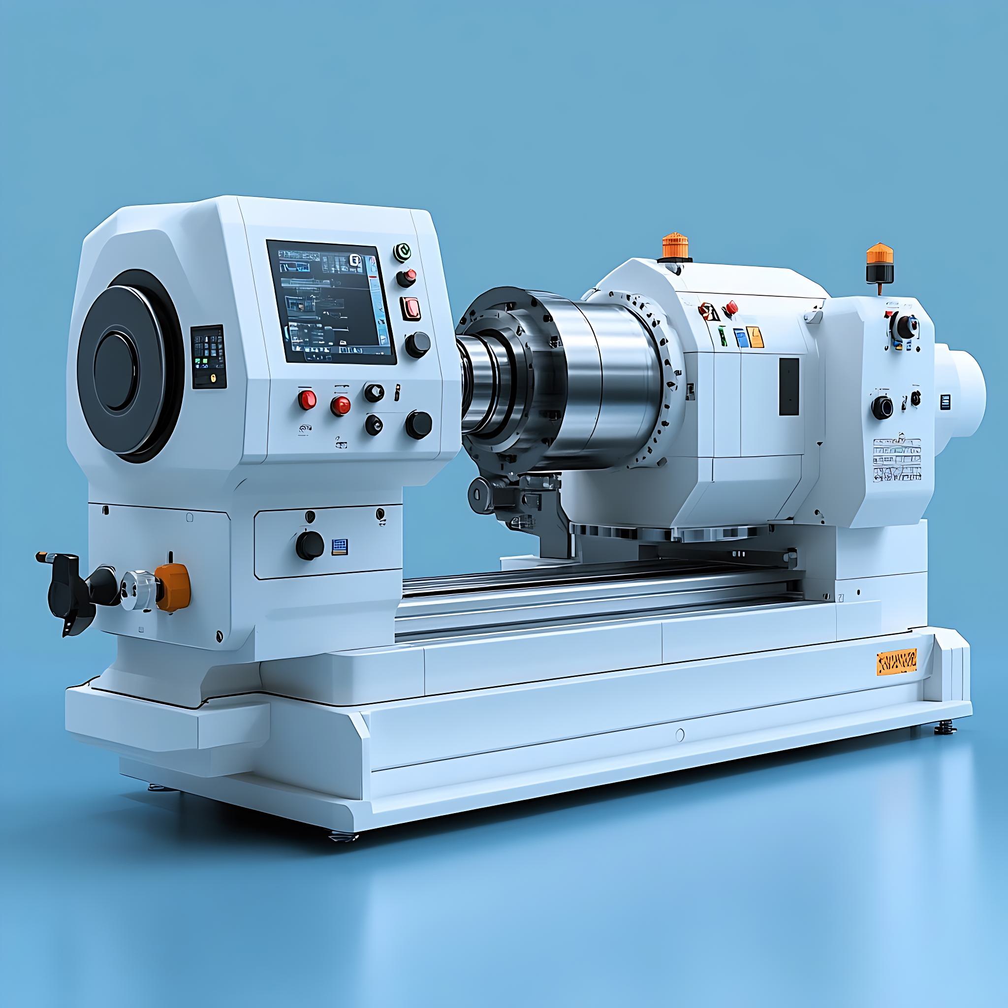
How the 90-Degree Roller Arrangement Transfers Radial, Axial, and Moment Loads
The defining feature is the alternating roller direction. One roller is positioned to react force components in one direction; the adjacent roller is turned 90 degrees to react components in the perpendicular direction. Under combined loading, the inner and outer rings transmit force through multiple roller contacts rather than relying on a separate thrust-bearing row.
The table below shows the load path that should be considered during early axis design.
| Applied load on the axis | How force enters the bearing | Transfer through the 90-degree roller arrangement | What the designer should verify |
|---|---|---|---|
| Radial load | A side force pushes the inner ring relative to the outer ring. | The roller orientation that faces the radial force carries the main contact load, while the crossed orientation helps retain ring guidance and system rigidity. | Check radial load direction, load position, duty cycle, and whether housing deflection changes the contact pattern. |
| Axial load | A force acts parallel to the axis of rotation, such as clamping force, gravity in a vertical axis, or machining thrust. | Rollers oriented to oppose that axial direction transmit load between the raceways. The alternating layout enables axial support in both directions. | Check maximum thrust in each direction. Reversing load may require attention to preload and lubrication condition. |
| Overturning moment | An offset load or cantilevered component attempts to tilt one ring relative to the other. | One side of the bearing is more heavily loaded while the opposite side reacts the separating force. The roller spacing across the bearing diameter provides the resisting couple. | Calculate the moment from force multiplied by offset distance, then assess ring stiffness, mounting-face flatness, and bolt pattern. |
| Combined radial, axial, and moment load | Several load components act together during one operating position. | The contact load is distributed unevenly among rollers according to direction, preload, structural stiffness, and ring deformation. | Use the actual load spectrum rather than checking each load independently at its maximum value. |
Practical conclusion: a crossed roller bearing is best suited to a compact axis that needs to resist force from several directions at one location. It is especially useful when a platform or arm creates a moment load around the bearing center. It is not enough, however, to confirm that radial, axial, and moment loads are each “within range” separately. Their simultaneous occurrence determines the most heavily loaded roller contacts.
For example, a horizontal indexing plate may have modest vertical weight when stationary. Once a fixture is installed away from the centerline, the fixture weight creates both radial loading and an overturning moment. During acceleration and deceleration, drive torque and inertia add further load components. The bearing selection should be based on those operating states, not the empty-table condition.
Which Bearing Parameters Affect the Rotary Axis Most?
Load capacity is only one selection input. A precision axis also depends on stiffness, running accuracy, preload, lubrication, and the rigidity of parts around the bearing. The following relationships help prevent a common mistake: choosing a bearing by nominal dimensions alone.
| Parameter | What it affects in operation | When it matters most | Selection limit or trade-off |
|---|---|---|---|
| Radial and axial load ratings | Basic ability to carry force through the rolling contacts. | Fixtures, vertical axes, pressing operations, and mechanisms with external side forces. | A rating alone does not describe tilt resistance or the effect of combined loading. |
| Overturning-moment capacity | Resistance to ring tilting and displacement under an offset load. | Cantilevered arms, rotary tables, tool fixtures, and camera or sensor platforms. | Housing and shaft deformation can reduce effective axis stiffness even when the bearing itself is suitable. |
| Preload or internal clearance condition | Rotational stiffness, backlash behavior, and resistance to vibration. | Robot joints, measurement equipment, precision indexing, and low-speed positioning. | More preload is not automatically better; it can increase friction torque and heat generation. |
| Accuracy class and runout | Rotation accuracy and repeatable positioning of the mounted component. | Grinding machines, optical inspection, semiconductor handling, and high-accuracy turntables. | Mounting faces, pilot diameters, and tightening sequence must preserve the achieved bearing accuracy. |
| Lubrication selection | Friction torque, wear control, and operating consistency. | High duty cycles, low-speed motion, reversing rotation, and clean operating spaces. | The lubricant must suit speed, temperature, contamination exposure, and maintenance access. |
Recommendation for a high-stiffness positioning axis: prioritize moment resistance, preload condition, and the stiffness of the supporting structure together. This fits a robot wrist, direct-drive turntable, or measuring axis where small angular deflection changes the end position. It may not be the right priority for a freely rotating, low-load mechanism where low friction is more valuable than maximum rigidity.
BY Bearings can provide precision classes up to P2 and controls runout within 1.5 μm through 100% inspection before shipment. Those manufacturing controls are relevant when the bearing is part of an accuracy-sensitive assembly, but the final installed runout still depends on the shaft shoulder, housing bore, mounting surfaces, and assembly process.
Why Combined Loads Change the Selection Result
Radial load, axial load, and moment load interact. The interaction becomes more pronounced when the external force is offset from the bearing center, when direction reverses, or when the mounting structure is relatively thin.
Offset distance can dominate the result
An external force at the bearing center creates force but little overturning moment. Move that same force outward on a fixture arm, and the moment rises in direct proportion to the offset distance. This is why a compact bearing may be acceptable for a centered payload yet unsuitable after a longer tool holder, workpiece fixture, or robotic link is added.
Action: list every significant mass and process force, then record its distance from the bearing center plane. Include the worst working position, not only the parked position. This approach fits any rotating axis with an overhung load. It is less relevant for a symmetric, centrally loaded rotor, where moment loading is naturally lower.
Preload supports stiffness but affects torque
Preload removes internal looseness and improves resistance to small reversals and vibration. That is useful when a rotary axis must hold repeatable position. Yet preload also increases rolling contact force, which can increase friction torque and thermal rise.
Action: state the required positioning behavior before specifying a preload condition. A precision inspection axis may favor a carefully controlled preload. A higher-speed axis or an energy-sensitive direct-drive system may need a different balance between stiffness and torque. Do not specify maximum preload simply because the system needs high load capacity.
Mounting structure is part of the bearing system
A crossed roller bearing transfers load into the shaft, housing, flanges, and fasteners. If these parts flex, the rings may lose uniform support. Local distortion can concentrate rolling contact load and reduce expected rotation accuracy.
Specify mounting-face flatness, bore geometry, pilot fit, bolt arrangement, and tightening sequence in the axis drawing. For applications needing a bearing built around rotary-table requirements, compare the available Rotary Table Bearings range as well as crossed roller options. A rotary-table bearing configuration may be a better fit where the table structure and mounting arrangement drive the selection.
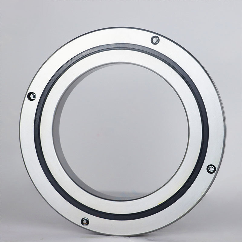
What Designers Often Misread About Single-Bearing Support
The most common misunderstanding is that a single crossed roller bearing eliminates the need for engineering checks around the rest of the axis. It can simplify the bearing arrangement, but it does not remove the need to calculate loads or verify the surrounding structure.
- Mistake: Checking only the payload weight. The payload may be small, while its offset, acceleration, cutting force, or clamping force creates the governing condition. Check each operating position and transient event.
- Mistake: Treating radial, axial, and moment ratings as separate pass/fail values. In service, the same rollers may experience combined effects. Provide the full load combination to the bearing supplier for assessment.
- Mistake: Assuming a larger bearing always improves axis accuracy. A larger size may improve stiffness potential, but it can add inertia, occupy more installation space, and require a more rigid housing. Select the size around the required duty, not diameter alone.
- Mistake: Ignoring reversing motion. Oscillation and frequent direction changes can make preload, lubricant choice, and friction consistency more important than in continuous rotation.
- Mistake: Copying the bearing fit from a different machine. Shaft and housing geometry, material, temperature, and bolt layout can change ring support. Use the bearing drawing and application conditions for the actual assembly.
A practical verification package should include the radial force, axial force in both directions, overturning moment, rotation speed, duty cycle, required runout, ambient temperature, lubrication preference, and installation drawing. If any of these inputs are missing, the result should be treated as preliminary rather than a final bearing selection.
For a machine-tool axis subject to cutting loads and fixture moments, see our application guidance for Bearings for Machine Tools. For compact robot joints, the relevant question is usually not only load capacity but also whether preload and mounting stiffness can control backlash under reversing torque.
A Practical Early-Stage Selection Procedure
Use this sequence when deciding whether BBH Crossed Roller Bearings can support your complete rotary-axis load case.
- Define the bearing location. Mark the bearing center plane and axis direction on the assembly drawing. All load distances should be measured from this reference.
- List external loads by operating condition. Include payload weight, tooling force, clamping force, belt or gear force, drive torque reaction, acceleration, and deceleration.
- Convert offset forces into overturning moments. For each force, multiply the force by its perpendicular distance from the bearing center. Keep the direction of each moment clear.
- Identify the combined worst case. The heaviest payload condition may differ from the highest process-force condition. Review start, stop, processing, and emergency-stop states where applicable.
- Set accuracy and stiffness requirements. Define allowable runout, tilt, backlash behavior, and torque expectations before choosing preload or accuracy class.
- Check the surrounding structure. Confirm that the shaft, housing, mounting faces, and fasteners can support the bearing rings without harmful distortion.
- Submit the application data for review. Include a drawing, load table, target service condition, and any special dimensional or mounting-hole requirements.
This method is well suited to early technical research because it separates the bearing question from the larger axis question without treating them as unrelated. It also helps determine when another design may fit better. For example, a compact, high-rigidity joint often favors a crossed roller arrangement, while a larger rotating structure with different installation constraints may call for Crossed Tapered Roller Bearings or another bearing configuration.
What to Request Before Releasing the Axis Design
Before approving a bearing for production, ask for the dimensional drawing, load-capacity information for the intended configuration, accuracy specification, preload or clearance condition, mounting guidance, lubrication recommendation, and inspection scope. Where custom dimensions or mounting holes are needed, provide the mating-part drawings early. BY Bearings supports OEM and ODM customization with no MOQ, which can help engineering teams validate a special interface before a larger production release.
A useful reference is the Mexico application involving P2 rotary table bearings for gear grinding. The appropriate lesson is not that every rotary axis requires P2 precision. It is that the precision class must match the process requirement. Gear grinding places demanding requirements on rotation accuracy, while a general automation fixture may be properly served by a different accuracy and cost balance.
For BBH Crossed Roller Bearings, the best decision comes from a complete load-path review: identify how force enters the axis, how far that force acts from the bearing center, how preload affects the required behavior, and whether the mounting structure can preserve the bearing’s accuracy.
Send BY Bearings your load table and assembly drawing to get a quote or request selection advice.
 +8618939019135
 sales@bybearings.com
 +8618939019135

