
How Bulk Crossed Roller Bearings Maintain Accuracy
How can one bearing support radial force, axial force, and overturning moment while still holding a rotary axis accurately? The answer lies in roller direction, raceway contact geometry, preload control, and the consistency of the bearing supplied across a production order. Precision Crossed Roller Bearings are designed for compact rotary assemblies where separate radial and thrust bearing arrangements would add space, interfaces, and potential alignment error.
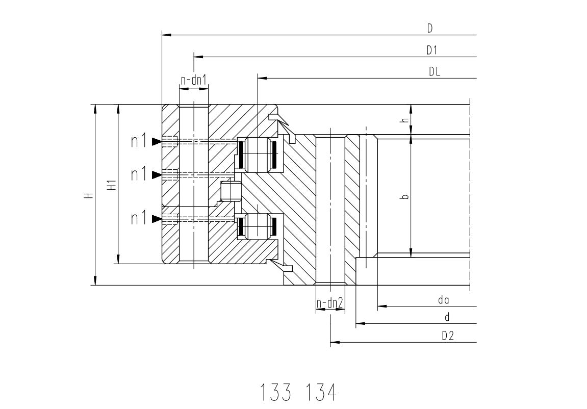
Bulk Crossed Roller Bearings maintain accuracy by using cylindrical rollers arranged alternately at right angles between precision raceways. This layout distributes combined loads through multiple rolling contacts, limits relative movement between the inner and outer rings, and gives the assembly high resistance to tilting. However, the bearing alone cannot guarantee final system accuracy. Housing geometry, shaft or mounting surface accuracy, tightening sequence, preload condition, lubrication, and inspection criteria all affect the result.
Start With the Accuracy Requirement and the Load Path
For early stage design work, do not begin by selecting only an outside diameter or bore size. Begin with the accuracy the rotary assembly must preserve and identify where external loads enter the structure. A crossed roller bearing is most effective when the design needs a compact bearing set to carry radial load, axial load, and moment load at the same time.
The phrase crossed roller bearing accuracy covers more than dimensional tolerance. In a rotary assembly, it usually includes radial runout, axial runout, tilt under load, rotational smoothness, and repeatable position after direction reversal. These results come from the whole bearing and mounting system.
| Design question | What it affects | Action during early evaluation | When this is not enough |
|---|---|---|---|
| Where does the working load act? | Moment load and local raceway loading | Map the force position relative to the bearing centerline. | Use detailed load calculation when force direction changes during operation. |
| What motion quality is required? | Runout, torque consistency, and repeatability | Specify the measurement item, reference surface, and inspection condition. | A general precision grade alone does not define installed accuracy. |
| Is the rotary structure stiff enough? | Deflection under external moment | Evaluate housing wall thickness, flange support, and fastener layout. | A stiff bearing cannot compensate for a flexible table or bracket. |
| Will the bearing be preloaded? | Clearance, rigidity, friction torque, and heat | Define the intended preload condition before requesting quotations. | Do not assume higher preload always produces better operating results. |
The practical conclusion is simple: choose the bearing type after defining the load path and acceptable motion error. This approach fits CNC rotary axes, robotic joints, direct drive tables, inspection fixtures, and semiconductor handling equipment. It does not replace a full structural calculation where high acceleration, shock loading, or unusual mounting geometry is present.
BY Bearings supplies crossed roller bearings, harmonic drive bearings, crossed tapered roller bearings, rotary table bearings, slew bearings, thin section bearings, spherical roller bearings, cylindrical roller bearings, and thrust bearings. For a machine tool axis with high tilting force, a dedicated Rotary Table Bearings option may be more suitable than selecting a general crossed roller configuration based on size alone.
How Roller Orientation Raceway Geometry and Preload Preserve Accuracy
The three mechanisms below work together. Looking at only one of them can lead to an incorrect selection. Alternating roller direction creates multi direction load support, raceway geometry controls how force is transferred into the rings, and preload controls how much internal movement remains before the assembly is loaded.
| Accuracy mechanism | What it does under combined loads | Practical consequence | Trade off or limit |
|---|---|---|---|
| Alternating roller orientation | Rollers arranged at right angles accept force components in different directions. | One compact bearing can resist radial, axial, and overturning loads. | Load capacity still depends on bearing size, contact conditions, and applied force location. |
| Precision raceway geometry | Guides rollers along defined contact paths and shares force across rolling elements. | Reduced relative ring displacement helps retain rotary axis position. | Poor mounting surface form can distort the rings and reduce this benefit. |
| Stable preload | Removes unwanted internal clearance and keeps rollers engaged when direction changes. | Improves response to reversal and raises resistance to small tilting movement. | Excessive preload can increase friction torque and heat generation. |
Alternating roller direction resists moment induced tilt
The crossed roller bearing roller arrangement places adjacent cylindrical rollers in alternating directions. When an external load tries to tilt the rotating ring, the bearing does not rely on a single contact orientation to oppose that motion. Instead, different roller groups react to the force components created by the moment.
This is why crossed roller bearings are often selected for compact rotary tables and robotic joints. A workpiece mounted away from the bearing centerline creates a lever arm. The farther the load acts from that centerline, the more the bearing and surrounding structure must resist tilt. The bearing can carry that moment, but the housing must provide a flat, rigid support surface so the ring remains properly seated.
The conclusion is not that every crossed roller bearing is automatically appropriate for high moment service. For heavy rotary tables, large cutting forces, or demanding turn mill applications, evaluate bearing size, ring section, mounting bolt pattern, support flange stiffness, and operating cycle together. Bearings for Turn Mill Centers require this system level assessment because process forces can change direction while the table rotates.
Raceway geometry controls contact stability
Raceways do more than provide a rolling surface. Their geometry determines where rollers contact the rings and how force is carried through those contacts. Uniform geometry supports consistent roller loading. When the load is distributed as intended, local deflection is reduced and the rotating ring is better able to hold its position.
In practice, raceway performance is affected by the ring itself and by the mounting condition. A bearing mounted on a surface with burrs, dirt, uneven support, or distorted bolt tightening can lose the geometric relationship established during production. This can create uneven torque, local stress, or a measurable change in runout after installation.
BY Bearings uses premium GCr15 bearing steel and applies metallographic examination after heat treatment to verify hardness and a stable martensitic structure. These controls support the material foundation required for precision raceways, but they do not eliminate the need for correct customer mounting. The bearing should be handled and installed as a precision component, not as a general mechanical spacer.
Preload stabilizes direction reversal
Preload is the internal condition that keeps rolling elements engaged before the external working load is applied. In a precision rotary axis, this matters when motion reverses. If internal clearance allows the rings to shift slightly before rollers take load, the driven component can show lost motion or unstable positioning.
A controlled preload improves crossed roller bearing rigidity because the rings resist relative displacement earlier in the load cycle. This is useful for index tables, robot wrists, optical positioning structures, and direct drive turntables where small angular movement can affect process quality.
The limit is equally important. More preload is not automatically more accurate in operation. Too much preload raises friction torque and can add heat. Thermal change may then alter the condition that the preload was intended to stabilize. Specify preload based on motion speed, duty cycle, lubrication, ambient condition, drive torque, and allowable thermal behavior.
Control Production Consistency When Buying for Inventory
A design engineer sourcing inventory needs more than a catalog dimension. Bearings intended for the same assembly should have consistent accuracy characteristics, controlled materials, and repeatable inspection records. Otherwise, a machine builder may spend unnecessary time adjusting mounting parts, torque settings, or assembly procedures from batch to batch.
For precision applications, ask the supplier what is inspected before shipment and how results are tied to the order. BY Bearings operates under an ISO 9001 quality system and performs 100% inspection before shipment. For specified precision products, grinding accuracy can reach P2 class and runout is controlled within 1.5 μm. These figures are relevant only when matched to the correct product requirement and inspection condition; they should not be treated as an automatic installed system result.
Use the following procurement procedure before releasing a recurring order.
Define the mounting envelope. Provide bore, outside diameter, width, mounting holes, reference faces, and assembly orientation.
Describe all applied loads. Identify radial force, axial force, overturning moment, direction changes, and the point where each load enters the structure.
State the required motion result. Specify whether the priority is runout, tilt resistance, low torque, repeatability, or a balance of these requirements.
Confirm the intended precision and preload condition. Ask for the applicable grade and define whether the assembly needs clearance, normal preload, or a specified preload arrangement.
Request inspection evidence. Confirm which runout, torque, or dimensional checks will be reported and how the bearing is referenced during measurement.
Validate one assembly first. Install a first article using the planned housing, fasteners, tightening pattern, lubrication, and drive arrangement.
Release the inventory specification. Freeze the drawing, inspection items, packaging requirements, marking, and approved substitution rules.
This process fits OEM inventory planning and repeated machine builds. It may be shortened for a prototype, but skipping the installed validation stage can be costly when the final structure has thin support walls or a highly offset working load.
Prevent the Misunderstandings That Reduce Installed Accuracy
The most frequent selection error is assuming that a precision bearing grade by itself determines machine accuracy. A precision grade reflects controlled bearing characteristics, while machine accuracy is the outcome after mounting, loading, driving, and thermal exposure. The distinction matters when an assembly is evaluated at low speed without load and later used under a changing production load.
Mistake: Selecting by dimensions only. A bearing may fit the envelope but lack the needed moment resistance. Review the load offset and support structure before final selection.
Mistake: Treating preload as a universal improvement. Preload reduces internal movement, but friction torque and heat must remain acceptable for the application.
Mistake: Ignoring mounting face quality. Precision rings need clean, flat, fully supported reference surfaces. Check for burrs, contamination, dents, and uneven tightening.
Mistake: Measuring runout from an uncontrolled reference. Measure from the functional locating surface and document the clamping condition so results can be compared.
Mistake: Mixing lots without traceability. For repeat builds, retain lot identification and inspection information so an assembly issue can be investigated efficiently.
Mistake: Applying a low torque requirement without defining speed and lubrication. Friction behavior depends on operating conditions, not only on the bearing part number.
A useful verification approach is to measure the assembly at three stages: after bearing mounting, after drive integration, and under representative working load. If runout changes after drive installation, investigate coupling alignment, motor support, belt or gear force, and fastener sequence before changing the bearing specification.
Apply the Mechanism to Rotary and Automation Assemblies
Consider a precision rotary fixture where the workpiece is positioned away from the rotation center. The workpiece weight creates a moment that attempts to tilt the table. During indexing, the drive reverses direction and any internal clearance can appear as position variation. A crossed roller arrangement addresses the combined load condition, while preload helps control reversal movement. The housing and table plate must still resist bending, or the full benefit of the bearing will not reach the work surface.
For high precision rotary applications, BY Bearings has supplied P2 rotary table bearings for gear grinding in Mexico. That case shows the relevance of precision class and controlled runout in a specific gear grinding application. It should not be interpreted as a blanket specification for every rotary table, because required bearing size, loading, speed, and mounting design differ by machine.
Where the application is a compact automation axis rather than a heavy table, the selection may favor a low profile crossed roller configuration. Where the rotary structure must carry more demanding machining forces, review BRTM Series Rotary Table Bearings alongside the machine structure and duty cycle. For harmonic reducer assemblies, the relevant system constraints may differ, including compact integration and the effect of preload on drive behavior.
Use a Drawing Based Review Before Committing to Stock
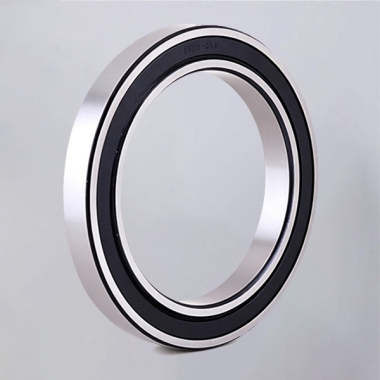
The strongest inventory decision is based on the installed assembly, not an isolated bearing catalog entry. Submit the bearing envelope, mounting section, load directions, desired accuracy grade, speed range, lubrication method, operating temperature conditions, and inspection requirements. These details allow the supplier to identify whether a standard series fits or whether OEM and ODM customization is needed.
BY Bearings supports flexible customization for precision bearing applications, with quality controls that include pre shipment inspection. For an engineering review of your rotary assembly, get a quote with your drawing and required inspection items.
 +8618939019135
 sales@bybearings.com
 +8618939019135

