How High Precision Crossed Roller Bearings Cut Runout
What is Bearing Runout and Why Does It Matter?
In any rotating system, runout is the total variation in a desired plane of rotation as the axis turns 360 degrees. For engineers designing CNC rotary tables, robotic joints, or medical imaging equipment, excessive runout directly translates to positioning errors, surface finish defects, and poor repeatability. It is the enemy of accuracy. We can measure it in two primary forms:
Axial Runout: The "wobble" or out-of-plane deviation of the bearing face.
Radial Runout: The "off-center" deviation of the bearing's outer or inner diameter as it rotates.
While all bearings exhibit some level of runout, the unique internal geometry of Precision Crossed Roller Bearings is specifically designed to minimize these deviations. Their construction, featuring cylindrical rollers arranged orthogonally between V-grooved raceways, provides exceptional rigidity against radial, axial, and moment loads from a single, compact unit. This inherent stiffness is the first step in controlling runout, but achieving micro-radian positioning accuracy requires a deeper look at how the bearing's components and its installation environment work together.
The Four Pillars of Runout Control
Achieving low runout isn't the result of a single feature; it's the sum of meticulous control over multiple interacting variables. A bearing's final rotational accuracy is a direct consequence of its internal precision and the quality of its installation. Understanding these four factors is critical for any engineer specifying a high-accuracy rotary system.
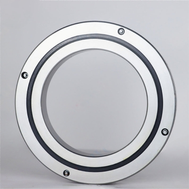
Here is a technical breakdown of how these elements combine to control the final measured runout:
| Factor | Technical Impact | Practical Consequence |
|---|---|---|
| 1. Roller Grade & Uniformity | Rollers are graded based on their diameter and geometric consistency. Higher grades have tighter diameter tolerances (within 1-2 μm). We sort rollers into matched sets to ensure uniform load distribution across the contact line. | Inconsistent roller diameters create high and low spots as the bearing rotates, causing torque fluctuations and micro-vibrations that manifest as runout. A uniformly graded set ensures smooth, continuous contact. |
| 2. Raceway Geometry & Finish | The precision grinding of the V-groove raceways is paramount. This includes the groove's angle, depth, and surface finish. Deviations in the raceway path force the rollers to move axially or radially, directly creating runout. | A perfectly ground raceway acts as an ideal guide path. Any imperfection, even at a microscopic level, will be "felt" by the rollers and transmitted as motion error. This is why our grinding processes achieve P4 and P2 precision levels. |
| 3. Mounting Face Flatness & Perpendicularity | A crossed roller bearing's thin-walled rings are designed to conform to the mounting surfaces. If the housing or shaft face is not perfectly flat and perpendicular to the axis of rotation, it will distort the bearing rings when clamped. | This is the most common external cause of increased runout. A 5 μm deviation in housing flatness can easily translate into a 2-3 μm increase in the bearing's measured runout. The bearing cannot compensate for a poor mounting foundation. |
| 4. Preload (Negative Clearance) | Preload is the application of a sustained axial force that removes the internal clearance in a bearing. In crossed roller bearings, this is carefully set during manufacturing to create a specific "negative clearance," ensuring the rollers are always in firm contact with both raceways. | Without sufficient preload, rollers can shift slightly under changing loads, causing minute wobbles and a loss of rigidity. Proper preload eliminates this "play," drastically increasing stiffness and minimizing deflection-based runout under load. |
Manufacturing Controls for Superior Rotational Accuracy
The theoretical principles of runout control are only as good as the manufacturing processes that implement them. At BY Bearings, we have built our entire production system around achieving the highest levels of precision. Our commitment to quality is not just a final inspection; it's embedded in every stage of manufacturing.
It begins with the raw material. We use only high-grade GCr15 (SAE 52100) bearing steel, with each batch verified by spectrographic analysis to confirm its chemical purity. After our automated heat treatment process, we perform metallographic examinations to ensure a stable martensitic microstructure and optimal hardness of HRC 60-64. This provides the stable, wear-resistant foundation necessary for precision raceway grinding.
Our CNC grinding workshop is where this potential is realized. We can achieve grinding accuracy up to P2 class, but the ultimate proof is in the final measurement. That is why we enforce a strict policy of 100% inspection before shipment. Every single bearing is tested to ensure its runout is controlled within our maximum tolerance of 1.5 μm. This entire process is managed under our ISO 9001:2015 certified Quality Control system, giving our customers documented assurance of performance.
This rigorous process allows us to serve demanding applications, such as the P2 precision Rotary Table Bearings we supply to a gear grinding machine manufacturer in Mexico, where sub-micron runout is essential for producing accurate gear tooth profiles.

Common Mounting Mistakes That Negate Bearing Precision
You can specify the highest precision bearing in the world, but poor installation practices can easily double or triple the final system runout. As an application manager, I see engineers encounter these preventable issues frequently. Avoiding them is key to realizing the full accuracy potential of your components.
Here are the most common mistakes and how to prevent them:
Mistake: Uneven or Incorrect Bolt Tightening.
Problem: Tightening mounting bolts in a simple circular pattern can warp the bearing's thin outer ring, much like improperly tightening lug nuts on a car wheel. This distortion is a primary cause of increased runout.
Solution: Always tighten bolts in a star or crisscross pattern in three to four incremental steps. Use a calibrated torque wrench to apply the final, uniform torque specified in the bearing's manual. This ensures even clamping pressure.
Mistake: Contamination Between Mating Surfaces.
Problem: Even a small metal chip, burr, or piece of dirt trapped between the bearing ring and the housing/shaft surface creates a high spot. This introduces a tilt that directly translates into axial runout (wobble) with every rotation.
Solution: Thoroughly clean and deburr all mounting surfaces before installation. Wipe them down with a lint-free cloth and a suitable solvent. The surfaces should be perfectly clean and dry before the bearing is mounted.
Mistake: Out-of-Spec Housing and Shaft Geometry.
Problem: The bearing relies on the housing and shaft for its alignment. If the mounting shoulder is not perpendicular to the bore, or the mounting face is not flat, the bearing will be forced into a distorted state once installed.
Solution: Machine all mounting surfaces to the flatness, perpendicularity, and cylindricity tolerances recommended in the bearing datasheet. Verify these dimensions before assembly. Investing in better machining upfront saves significant troubleshooting time later.
This attention to detail is why clients in demanding sectors, like the German semiconductor equipment manufacturer we supply, rely on our bearings. In their wafer-handling systems, even the slightest vibration or positioning error from runout can lead to a failed process. By combining our precision bearings with proper installation, they achieve the stability they need.
Beyond our standard catalog, we also provide OEM and ODM services. If your application has unique mounting requirements or space constraints, we can customize dimensions and mounting holes to ensure a perfect fit, simplifying your assembly process and helping to reduce sources of system error.
If you have questions about your specific application's runout requirements or need guidance on mounting procedures, our engineering team is ready to assist. Send us your drawings to get a quote and a technical review.
 +8618939019135
 sales@bybearings.com
 +8618939019135