
How RB Series Crossed Roller Bearings Control Torque
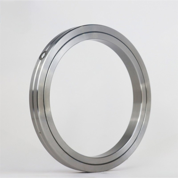
Machine designers often ask why a rotary axis can meet positional accuracy requirements yet still feel inconsistent during slow rotation. The answer is frequently found in the bearing’s friction behavior, preload condition, mounting accuracy, and rolling element arrangement. RB Series Crossed Roller Bearings are designed for compact precision rotary assemblies where stable rotational resistance matters alongside radial, axial, and moment load capacity.
BY Bearings supplies crossed roller bearings, harmonic drive bearings, crossed tapered roller bearings, rotary table bearings, slew bearings, thin section bearings, spherical roller bearings, cylindrical roller bearings, and thrust bearings for industrial motion systems. For designers comparing compact bearing options, our Precision Crossed Roller Bearings provide a useful starting point for evaluating rigidity, mounting requirements, and torque behavior.
Torque control is not simply about achieving the lowest possible friction. A bearing for a robot wrist, indexing unit, inspection table, or compact rotary stage needs predictable resistance throughout rotation. The goal is stable rotational torque: resistance that remains controlled and repeatable instead of changing noticeably as the axis turns.
Start by Separating Starting Torque from Running Torque
When evaluating crossed roller bearing torque, first distinguish between starting torque and running torque. Starting torque is the resistance that must be overcome when a stationary axis begins to move. Running torque is the resistance felt after rotation has started. Both affect servo tuning, motor selection, and positioning behavior, but they create different design concerns.
Choose a bearing with controlled torque variation when the axis moves slowly or pauses frequently. This fits inspection devices, semiconductor handling equipment, precision rotary fixtures, and robotic joints. In these applications, the motor may repeatedly accelerate from rest, reverse direction, or settle at a commanded position. An uneven starting condition can appear as a small motion delay or an unstable response in the control system.
Do not treat low friction as the only selection target. A very lightly loaded bearing may rotate freely, but it may not provide the rigidity required to resist overturning moments. Conversely, a high preload can increase rigidity while also increasing friction and motor demand. The correct choice depends on the full load case, required axis stiffness, drive capability, lubrication method, and mounting quality.
| Torque Condition | What It Affects in Practice | Best Design Response | Limit of the Approach |
|---|---|---|---|
| Starting torque | Breakaway motion, servo response, low speed starts | Specify suitable preload and verify installation geometry | Low starting resistance alone does not confirm sufficient rigidity |
| Running torque | Motor current, heat generation, continuous motion smoothness | Match lubrication and bearing selection to duty cycle | Running behavior can change if mounting faces distort the rings |
| Torque variation | Speed stability, surface quality, sensor accuracy | Control mounting accuracy and inspect the complete rotary assembly | A bearing inspection cannot replace system level testing |
| Preload related torque | Rotational stiffness and resistance to vibration | Define preload according to actual load and motion needs | Excess preload can raise friction and operating temperature |
For machine tool rotary axes exposed to combined loads, a dedicated rotary bearing may be more appropriate than an RB type. Designers can compare Rotary Table Bearings when the application demands a bearing arrangement developed specifically for turntables and rotary positioning equipment.
How the Split Outer Ring Spacer Retainer and Crossed Roller Layout Control Friction and Stable Rotational Torque
The internal design of an RB bearing determines how loads travel through the rolling elements and how friction is generated during rotation. Three construction features deserve close attention: the split outer ring, the spacer retainer, and the crossed roller layout. Each affects practical torque behavior in a different way.
| Construction Feature | Effect on Friction | Effect on Stable Rotational Torque | What Can Go Wrong in Selection or Assembly |
|---|---|---|---|
| Split outer ring | Allows the outer ring construction to be assembled around the rolling elements | Supports correct internal geometry when the ring is mounted evenly | Uneven screw tightening or an inaccurate housing seat can distort the ring and change rotational resistance |
| Spacer retainer | Keeps adjacent rollers separated and reduces direct roller contact | Helps maintain orderly roller movement during rotation | Ignoring lubricant condition or contamination control can reduce the benefit of controlled roller separation |
| Crossed roller layout | Rollers are arranged at alternating directions to carry loads from more than one direction | Helps resist radial load, axial load, and overturning moment within one compact bearing | Selecting only by envelope size can leave the assembly under supported for its applied moment load |
Why the split outer ring matters after installation
The split outer ring is not merely a manufacturing feature. It affects how the bearing responds to the housing and clamping arrangement. In a precision assembly, the housing shoulder, mounting surface flatness, screw tightening sequence, and local stiffness all influence whether the ring remains properly supported.
Use a rigid, accurately machined housing seat when torque consistency is a priority. This recommendation fits direct drive tables, compact rotary stages, and indexing axes where the bearing is mounted directly into a structural component. The reasoning is simple: a distorted support surface can change internal contact conditions as the bearing rotates.
This does not mean every design needs the same housing construction. A lightly loaded manual positioning unit may accept a simpler arrangement than a high duty automated axis. However, designers should not assume that a precision bearing will compensate for an imprecise housing or uneven clamping load.
Why the spacer retainer supports smoother motion
A spacer retainer separates the rollers so they do not crowd each other during operation. This controlled spacing supports orderly rolling behavior and helps reduce friction changes associated with roller interaction. For slow rotational motion, this can be especially relevant because torque variation is more noticeable when the axis moves at low speed.
Select a spacer retainer arrangement when stable motion is more valuable than simply minimizing bearing package size. It is well suited to measuring equipment, optical positioning units, and precision automation. It is less decisive when the application has broad motion tolerances and torque variation has little effect on process output.
Why the crossed roller layout carries combined loads
The crossed roller layout places cylindrical rollers in alternating directions. That arrangement allows a single bearing to support radial loads, axial loads in both directions, and overturning moments. In practical machine design, this can simplify the rotary structure because one bearing can address several load directions at once.
The benefit is most relevant when installation space is limited and the rotating member experiences a cantilevered load. Examples include robot joints, compact gear reducers, pick and place axes, and inspection tables. If the application is mainly a high speed radial shaft with limited moment load, another bearing style may be a better fit.
Select Preload for the Actual Rotary Task
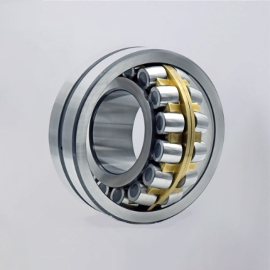
Preload is one of the strongest influences on rotational torque stability. It removes internal clearance and increases support stiffness, but it also raises rolling resistance. The correct preload is not the highest available condition. It is the preload that provides the needed axis stability without creating unnecessary friction, heat, or motor demand.
Use a higher preload direction when the assembly must resist vibration or repeated reversing loads. This can suit a robot arm joint, a compact machining fixture, or a direct drive rotary stage with an offset payload. The reasoning is that internal clearance can allow small movement under changing load direction. Preload limits that movement.
Use a moderate preload direction when the application prioritizes smooth continuous rotation and limited drive torque. This may suit a measuring table or low load positioning unit. The limit is that a lower preload may provide less resistance to applied moment loads and external vibration.
- Define the load direction. Identify radial, axial, and overturning moment loads instead of listing only the total supported mass.
- Check the duty cycle. Frequent reversals, slow speed motion, and continuous rotation create different torque requirements.
- Confirm drive capacity. The motor and reducer must handle bearing resistance together with payload inertia and process forces.
- Specify mounting conditions. Include shaft seat, housing seat, clamping method, and screw tightening procedure in the design review.
- Validate the assembled axis. Measure torque behavior after installation because surrounding structure affects the final result.
For higher combined loading in machine tool applications, designers can also assess Crossed Tapered Roller Bearings. Their selection should still be based on the actual axis load case and required motion behavior rather than a direct size comparison alone.
Avoid Mounting Errors That Change Rotational Resistance
Many torque concerns are created after the bearing leaves the factory. Even a correctly selected bearing can show inconsistent rotation when the mounting structure introduces deformation, contamination, or uneven clamp load. The bearing should therefore be treated as part of a complete precision assembly.
Common mistakes during rotary axis design
- Using the bearing as a correction for weak structure. A crossed roller bearing can provide high rigidity, but it cannot remove deflection from a thin housing, flexible flange, or unsupported payload.
- Ignoring overturning moment. A centered mass and an offset tool can have very different effects on the same bearing. Calculate the actual load position relative to the bearing center.
- Applying uneven clamping force. Tightening mounting screws without a controlled sequence can introduce local distortion into the ring support.
- Choosing lubricant without reviewing motion conditions. Lubrication influences friction behavior, particularly for low speed and repeated reversal applications.
- Measuring torque only before installation. Free rotation on a bench does not represent the torque of the complete machine axis.
- Leaving contamination control unspecified. Dust, chips, or unsuitable handling practices can affect rolling contact behavior and service consistency.
The practical conclusion is to review bearing, structure, drive, and assembly instructions together. This approach fits any precision motion system where torque affects motion quality. It may be less necessary for general rotation equipment with broad speed and positioning tolerances, but it remains good engineering practice.
Use Supplier Quality Evidence When Torque Stability Matters
For early stage research, buyers should ask not only which bearing type fits the envelope, but also how the supplier controls accuracy before shipment. Torque behavior is linked to geometry, rolling element matching, heat treatment, grinding, inspection, and final handling. A technical quotation should therefore include enough information to review the bearing against the intended assembly.
BY Bearings has more than 15 years of precision bearing manufacturing experience and operates a 13,500 m² intelligent factory with a CNC workshop and automated heat treatment line. Our ISO 9001 quality system supports controlled production and 100% inspection before shipment. Grinding accuracy is available up to P2 class, with runout controlled within 1.5 μm for applicable precision bearing requirements.
These production controls matter most for precision rotary assemblies where the designer is managing positional stability, low vibration, and controlled rotational resistance at the same time. They do not eliminate the need for correct installation, lubrication selection, and system testing. The completed machine still determines the final torque behavior seen by the motor.
A relevant application example is BY Bearings’ supply of P2 rotary table bearings for gear grinding equipment in Mexico. This case supports our experience with precision rotary bearing requirements in demanding grinding applications. It should not be treated as a universal performance promise for every machine, because each axis has its own loading, drive, and mounting conditions.
Our Quality Control process is especially relevant when buyers need to align bearing accuracy with the requirements of a precision motion platform. OEM and ODM customization is also available for special dimensions and mounting requirements, with no minimum order quantity stated for applicable projects.
Build an RFQ That Supports a Useful Torque Recommendation
A bearing supplier can provide more useful selection guidance when the inquiry describes the rotary system rather than only requesting a part number. For an RB style bearing, the following checklist helps engineers receive a technically relevant proposal.
- Provide the required inside diameter, outside diameter, width, and available installation envelope.
- State the radial load, axial load, and overturning moment, including the direction of each load.
- Describe whether rotation is continuous, indexed, oscillating, or frequently reversing.
- Identify whether smooth low speed motion, positioning repeatability, stiffness, or motor efficiency is the leading priority.
- Provide the drive type, such as direct drive motor, servo motor with reducer, or manual mechanism.
- Share the shaft and housing drawings, including shoulders, mounting holes, and clamping surfaces.
- Specify the operating environment, including cleanliness expectations and lubrication preferences.
- Request the required precision class and any runout requirement for the assembled axis.
This checklist is most useful for machine designers working on precision rotary assemblies at the concept or prototype stage. For replacement parts where dimensions and operating conditions are already confirmed, a shorter inquiry may be sufficient. Still, including application details helps prevent a bearing from being selected only by size.
For a compact rotary axis that requires combined load support and controlled motion behavior, submit your drawings and operating conditions to get a quote from BY Bearings.
 +8618939019135
 sales@bybearings.com
 +8618939019135

