
How Thin Section Bearings Save Space and Weight
How can a machine designer reduce rotating mass and installation space without redesigning the entire motion system? The answer often starts with the bearing envelope rather than the motor, housing, or frame. Thin Section Bearings use a cross section that remains consistent across a range of bore sizes, allowing larger diameters without the proportional increase in radial and axial packaging space seen in conventional bearing arrangements.
This geometry can help early-stage design teams create lighter robot joints, compact optical platforms, medical equipment, inspection systems, and direct drive assemblies. However, a smaller bearing envelope is not automatically the right answer. Load direction, moment loading, stiffness, mounting accuracy, sealing needs, and lubrication all determine whether this bearing style will perform as intended.

Compare constant cross sections with conventional bearing envelopes
Conclusion: Choose a constant-section design when a large rotational diameter must fit inside a restricted radial envelope. The main benefit is not simply a thinner ring; it is the ability to increase bore diameter while keeping the bearing section relatively unchanged. This can reduce both surrounding housing material and rotating structure mass.
In a conventional bearing family, the cross section generally grows as bore diameter grows. A larger shaft or central opening therefore requires a wider and taller bearing, a larger housing, and more material around the rotating axis. With constant cross section bearings, the designer can preserve more open space through the center of the assembly.
| Envelope factor | Thin section arrangement | Conventional bearing arrangement | What it affects in practice |
|---|---|---|---|
| Cross section as bore increases | Remains consistent within the bearing series | Usually increases with bore diameter | A large central opening can be retained without proportionally enlarging the support structure. |
| Radial package space | Lower radial profile for a given large diameter concept | More housing wall and surrounding clearance may be required | Reduces the outside diameter of rotating modules, sensor heads, and compact joints. |
| Axial stack height | Can reduce the height of a single-bearing support arrangement | May require a larger bearing or paired bearings | Helps when a motor, encoder, gearbox, and bearing must fit in a shallow assembly. |
| Rotating mass | Less ring and housing material may be needed | Larger rings and housings can add mass | Can reduce inertia, which matters for indexing axes and weight sensitive equipment. |
| Central access space | Large through bore is easier to package | Central passage can become restricted | Allows cables, pneumatic lines, optics, shafts, or fluid connections to pass through the axis. |
| Mounting sensitivity | Requires accurate support surfaces and controlled distortion | Often has more structural section around the rings | Thin rings can lose running accuracy if the housing or shaft is out of round. |
The mass saving is therefore system-level, not just bearing-level. If a bearing allows a smaller housing diameter, shorter mounting flange, and lighter rotating plate, the assembly can save more mass than the bearing alone. This is particularly useful in compact motion systems where the actuator must accelerate and stop repeatedly.
The limit is stiffness. A thin ring does not compensate for a weak housing. If the surrounding structure flexes under load, the bearing raceways can distort, causing uneven rolling contact, torque variation, wear, or reduced positioning consistency. Designers should assess the bearing, shaft, housing, fasteners, and mounting faces as one support system.
Match load direction to the bearing contact design
Conclusion: Select the contact configuration from the real load path, not from envelope size alone. A compact bearing may fit the drawing but still be unsuitable if it receives axial thrust, radial force, and overturning moment that do not match its contact geometry.
There are several common arrangements. Radial designs primarily support radial loading. Angular contact bearings support combined radial and axial loads in a preferred direction, and they are commonly paired when thrust can reverse. Four-point contact designs can accept radial load, axial load in both directions, and moment load in one bearing location. This can simplify a turntable or articulated joint that otherwise requires multiple bearings.
| Contact arrangement | Best-fit loading condition | Design advantage | When not to use it alone |
|---|---|---|---|
| Radial contact | Mainly radial force with limited thrust | Simple support for rotating rings and pulley-style loads | Do not rely on it where sustained axial thrust or a large overturning moment is present. |
| Angular contact | Combined radial and one-direction axial loading | Suitable for controlled axial location and paired arrangements | Do not assume one bearing handles reversing thrust unless the arrangement is designed for it. |
| Four point contact | Radial, axial, and moment loads acting through one bearing position | Can replace a more space-consuming paired arrangement | Do not use it as a shortcut when application loads require higher tilting stiffness than the full structure can provide. |
For example, a camera positioning ring with a large center passage may need a compact rotating support and modest loading. A four point contact arrangement may allow the designer to keep cables and optical paths through the middle while avoiding a wide pair of bearings. In contrast, a machine tool rotary axis under heavy cutting loads may need a dedicated rotary table arrangement because stiffness and runout control take priority over minimum wall thickness. In that case, review Rotary Table Bearings rather than forcing a thin bearing into a load case it was not selected to carry.
Getting this wrong has predictable consequences. Underestimating axial force can create raceway damage. Ignoring overturning moment can lead to angular deflection at the tool point or payload. Choosing a bearing with inadequate radial load capacity can shorten service life even when the assembly initially turns smoothly.
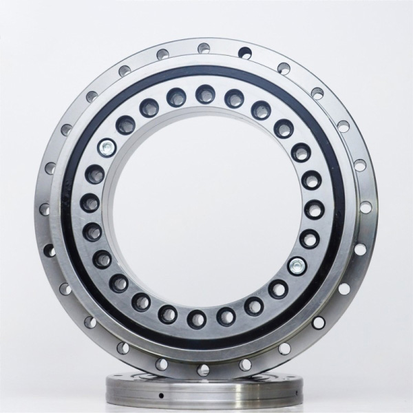
Use a practical selection workflow during concept development
Conclusion: Freeze the load path and mounting concept before requesting a final bearing size. This approach fits concept development because it prevents a catalog bore and outside diameter from becoming an expensive constraint before the real performance requirements are understood.
Map the available envelope. Record the allowed bore, outside diameter, axial height, central pass-through area, mounting flange location, and access needed for tools or fasteners. This defines the actual bearing envelope design.
Identify every load direction. Separate radial load, axial load, reversing thrust, and overturning moment. Include the load location because a force acting away from the bearing centerline creates a moment that changes ring deflection.
Determine whether mass or stiffness leads the decision. A lightweight robotic wrist may prioritize low inertia. A precision inspection table may prioritize rotational stability and low torque variation. These are different design targets.
Select the contact arrangement. Compare radial, angular contact, and four point contact geometry against the load map. Confirm whether a single bearing can locate the assembly or whether a paired arrangement is required.
Design the shaft and housing interfaces. Specify roundness, flatness, shoulder support, mounting hole positions, and fastening sequence. A thin bearing installed on distorted seats cannot maintain its intended geometry.
Confirm lubrication, seals, and environment. Cleanroom equipment, medical equipment, dusty production lines, and outdoor machinery require different protection strategies. Do not specify an open bearing when contamination control is uncertain.
Submit the drawing with operating conditions. Include speed, load directions, required accuracy, duty cycle, temperature exposure, and target installation space. This gives the supplier information needed to check the selection instead of merely matching dimensions.
A useful rule is simple: if reducing bearing mass forces the housing to become too flexible, the design has not achieved a real saving. The correct option is the lightest arrangement that still keeps deflection and running behavior within the equipment requirement.
Where very high rigidity and compact integration are required, crossed roller designs may be a better technical route than a conventional ball bearing layout. BY Bearings supplies Precision Crossed Roller Bearings for applications where combined loads and rotational accuracy must be managed in a compact structure. The trade-off is that the mounting surfaces and preload requirements need closer engineering attention.
Avoid common packaging and mounting mistakes
Conclusion: Treat the bearing as a precision component rather than a space-saving washer. Most avoidable failures begin with an incomplete load estimate, an unsupported ring, or a mounting surface that deforms the raceway.
Choosing by bore diameter only: A large through bore may look ideal, but the bearing must still support the radial, axial, and moment loads. Use the load map first; use the bore size second.
Ignoring housing rigidity: A thin housing can ovalize when bolts are tightened or external force is applied. This transfers distortion directly into the rings. Use adequately supported shoulders and uniform clamping.
Using one bearing to solve every problem: A four point contact option can save axial space, but it is not automatically suitable for every heavy moment load. Compare structural stiffness before removing a paired-bearing concept.
Leaving no mounting tolerance budget: The bearing, housing bore, shaft seat, flange face, and fastener pattern all contribute to assembled runout. Reserve tolerance budget across the complete assembly.
Forgetting service access: A compact package still needs installation clearance, lubrication access where applicable, cable routing, and a method to remove the bearing during maintenance.
Assuming lower mass always improves performance: Reduced inertia can improve response, but an under-supported bearing can introduce vibration or position error. Weight reduction should never replace stiffness verification.
These points matter especially in automation and semiconductor equipment. A German customer case supplied by BY Bearings involved crossed roller bearings for semiconductor equipment, where stable precision motion and controlled running behavior are central requirements. For applications with similar sensitivity, review the complete motion assembly rather than selecting on nominal envelope alone.
Verify supplier controls before approving a compact bearing design
Conclusion: When the bearing has limited structural section, supplier process control should be part of the engineering review. This is most relevant where rotation accuracy, torque consistency, or repeat positioning affects the finished machine.
Ask how steel quality, heat treatment, grinding, inspection, and shipment checks are managed. BY Bearings uses premium GCr15 bearing steel verified through spectrographic analysis and conducts metallographic examination after heat treatment. The stated hardness range is HRC 60 to 64. Its production controls also include grinding accuracy up to P2 class, runout control within 1.5 μm, and 100% inspection before shipment.
These controls are relevant to compact precision assemblies because ring geometry and raceway quality affect rotation behavior. They do not remove the need for correct mounting design. A high-accuracy bearing installed in an out-of-round housing will still be affected by the housing.
For sourcing teams, BY Bearings brings more than 15 years of precision bearing manufacturing experience, operates a 13,500 m² intelligent factory with CNC workshop and automated heat treatment line, and maintains a 15,000-set monthly production capacity. Its quality system is compliant with ISO 9001:2015, and CE, RoHS, and TUV certifications are available. OEM and ODM customization is also supported when standard mounting holes, dimensions, or interfaces do not match the project drawing.
Use this bearing selection checklist before releasing an RFQ:
Assembly drawing with bore, outside diameter, axial space, and central opening requirements
Radial, axial, and moment loading directions with load positions
Speed, duty cycle, lubrication method, and contamination exposure
Required runout, torque, stiffness, and positioning expectations
Housing and shaft material, wall thickness, and mounting method
Required certification, inspection documentation, and customization needs
For compact layouts that need a standard thin bearing format, see the Type A Thin Section Bearing. For machinery where the loads are better handled by tapered rolling elements, compare Crossed Tapered Roller Bearings before finalizing the architecture.
Send BY Bearings your assembly drawing and load conditions to get a quote and confirm the right compact bearing arrangement.
 +8618939019135
 sales@bybearings.com
 +8618939019135

