How to Choose Bearings for Semiconductor Equipment
Start with the motion error your semiconductor tool cannot accept
The main question when selecting Bearings for Semiconductor Equipment is not simply “which bearing fits the available space?” It is: which motion error will affect wafer position, process repeatability, or equipment uptime? A bearing for a wafer-transfer arm, inspection axis, rotary chuck, or wafer-handling stage must be selected from the required motion, combined load direction, speed profile, cleanliness requirement, and allowable positioning variation.
For compact rotary axes carrying radial, axial, and overturning loads, Precision Crossed Roller Bearings are often a practical starting point. Their perpendicular roller arrangement allows one bearing to support multiple load directions while keeping the mechanism compact. This suits many indexing, rotation, and articulated motion assemblies where stiffness and low runout matter.
However, a crossed roller arrangement is not automatically the right answer for every axis. A wafer cassette mechanism may prioritize compact radial support and low mass. A rotary inspection platform may prioritize tilting stiffness. A high-speed spindle-like module may need a different bearing system than a slow, high-precision wafer-positioning table. The correct selection follows the function of the axis, not the product category with the highest stated accuracy grade.
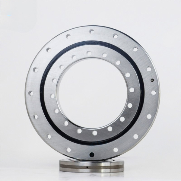
BY Bearings manufactures crossed roller bearings, harmonic drive bearings, crossed tapered roller bearings, rotary table bearings, slew bearings, thin section bearings, spherical roller bearings, cylindrical roller bearings, and thrust bearings. For semiconductor-related motion systems, crossed roller, thin section, and rotary table architectures are usually the most relevant starting points because they can address compact installation, multi-directional loading, and controlled rotational accuracy.
Selection matrix: match wafer-tool motion, load, speed, cleanliness, and bearing architecture
A bearing choice should be made by reading several conditions together. Motion type determines the direction and pattern of movement. Load determines deformation risk. Speed affects friction heat and lubricant behavior. Cleanliness defines what materials, lubrication methods, seals, and handling controls may be acceptable. These factors interact; selecting from only one of them can produce a mechanism that fits physically but performs inconsistently.
| Wafer-tool motion type | Typical load condition | Speed profile | Cleanliness class or requirement | Suitable bearing architecture | Why it fits and where it may not |
|---|---|---|---|---|---|
| Slow rotary wafer positioning or alignment | Radial, axial, and overturning moment loads | Low speed with frequent indexing | Particle-sensitive controlled environment | Crossed roller bearing | Supports combined loads in one compact unit and offers high tilting stiffness. It may not be the first choice when the application mainly needs a very thin radial section with minimal load. |
| Precision inspection turntable | Combined load with a stable moment load from fixtures or sensors | Low to moderate speed, repeated start-stop motion | Controlled environment with low vibration demand | Rotary table bearing | Designed for precision rotary motion and table-type assemblies. Confirm mounting surface accuracy and preload requirements before selection. |
| Compact wafer-transfer arm pivot | Moderate radial load, changing moment load during arm extension | Repeated acceleration and deceleration | Controlled environment with limited installation space | Thin section bearing or compact crossed roller bearing | Thin section designs help reduce envelope size and rotating mass. They may not provide the same moment stiffness as a properly sized crossed roller bearing. |
| Direct-drive rotary module | Radial and axial load with sensitivity to friction torque | Low-speed smooth rotation or programmed indexing | Particle-sensitive process area | Low-friction crossed roller bearing | A precision-matched roller arrangement can support smooth rotary movement. Final suitability depends on torque requirement, lubrication choice, and thermal conditions. |
| Heavier process fixture rotation | High overturning moment plus radial and axial loads | Low to moderate rotation speed | Environment dependent on tool location | Crossed tapered roller bearing or rotary table bearing | These architectures can be considered when stiffness under moment load drives the design. They require careful calculation of loading, mounting rigidity, and operating conditions. |
The practical rule is simple: choose the bearing architecture that controls the error mode most likely to damage process consistency. For a rotary wafer stage, tilt and runout may matter more than compactness. For a transfer arm, low rotating mass and installation space may have greater weight. For a direct-drive axis, friction torque and heat generation may become the deciding factors.
Cleanliness is not a separate checkbox added at the end. It changes the bearing specification itself. The engineering team should define whether the bearing will be located inside the process-facing area, behind a protective enclosure, or in a less controlled equipment zone. This decision influences lubricant selection, sealing approach, packaging, handling, and inspection expectations.
Understand how accuracy, stiffness, preload, and friction work together
High accuracy is useful only when the surrounding structure can preserve it. A precision bearing mounted on an uneven housing face or distorted by uneven bolt tightening can lose much of its intended motion quality. For semiconductor equipment, engineers should review the bearing, shaft, housing, mounting flange, fasteners, and drive system as one motion stack.
Runout affects the position of the rotating surface
Runout describes variation as a component rotates. In a wafer-handling or inspection mechanism, excess runout can appear as unwanted motion at the wafer plane, sensor interface, or fixture surface. The effect becomes more visible as the distance between the bearing centerline and the functional point increases.
BY Bearings controls runout within 1.5 μm and performs 100% inspection before shipment for applicable precision bearing supply. This is relevant for engineers who need measurable incoming-quality evidence rather than a general statement of precision. Still, bearing runout alone does not define final assembly runout. Housing geometry, mounting face flatness, shaft fit, clamp force, and fixture design can all change the assembled result.
Stiffness controls deflection under process loads
Stiffness is the bearing system’s resistance to displacement under load. In a rotary inspection table, low stiffness can allow angular movement when a camera, probe, cable assembly, or workholding fixture applies an overturning moment. The result may be focus variation, alignment drift, or unstable repeat positioning.
Crossed roller bearings are commonly selected when radial, axial, and moment loads act together because crossed rollers distribute these directions through one bearing structure. The trade-off is that mounting and preload must be defined correctly. Increasing preload may improve rigidity and reduce internal clearance, but it can also increase friction torque and heat. It is not correct to assume that maximum preload creates the best semiconductor motion axis.
Friction torque affects smooth motion and thermal stability
At low rotational speed, torque variation can cause uneven movement, especially in direct-drive or finely indexed systems. Heat generated by friction can also influence nearby components and change system behavior over time. A selection review should therefore include required starting torque, running torque consistency, duty cycle, acceleration pattern, and ambient temperature conditions.
For applications using a direct-drive motor, see the bearing considerations for Bearings for DD Motors. The bearing should not be selected independently of the motor, encoder location, cable routing, and rotary payload.

Choose the architecture by the failure mode you are trying to prevent
Engineers sometimes compare bearing types only by outside diameter, bore diameter, and nominal accuracy. That comparison misses the reason each architecture exists. The following guide links common semiconductor-tool requirements to a selection direction.
| Design requirement | Recommended direction | Reasoning | Do not use this as a shortcut when |
|---|---|---|---|
| One bearing must carry radial, axial, and moment loads | Crossed roller bearing | Perpendicular roller orientation supports combined load directions in a compact structure. | The load is almost entirely radial and the design is driven mainly by a very thin section. |
| Rotary table requires high rigidity and controlled rotary motion | Rotary table bearing | Suitable for precision turntables, indexing units, and table-like mechanisms. | Installation space or load direction makes another architecture more suitable. |
| Very limited radial envelope or low rotating mass | Thin section bearing | Helps designers reduce package size while providing rotational support. | A high overturning moment requires more stiffness than the selected thin section can provide. |
| High moment load on a fixture or larger rotating assembly | Crossed tapered roller bearing | Can be considered where load capacity and moment stiffness are central requirements. | Cleanliness, speed, mounting arrangement, and lubricant limits have not been defined. |
| Compact joint combined with a reduction mechanism | Harmonic drive bearing | Supports compact rotary joint integration where the drive architecture requires it. | The system is a stand-alone precision turntable rather than an integrated joint. |
For a table-style mechanism, Rotary Table Bearings provide a focused product direction. For a compact, multi-load rotary axis, engineers can compare product geometry and installation details within the crossed roller bearing range. The final decision should be based on the bearing drawing, load analysis, mounting arrangement, and cleanliness requirement—not a category name alone.
Prevent common specification mistakes before releasing the design
The most expensive bearing problems often begin during early specification, when the bearing is chosen before the real load path and installation conditions are known. Use the following checks during concept design and before sending a request for quotation.
Mistake: specifying accuracy grade without defining the functional measurement point. A high-grade bearing does not directly state the runout at the wafer plane. Define where the system will measure displacement, then include fixture height, mounting surfaces, and structural deflection in the calculation.
Mistake: treating radial, axial, and overturning loads as separate decisions. A wafer arm or rotary stage often generates all three at once. Provide the combined load condition and its direction over the operating cycle.
Mistake: requesting high preload without a torque limit. Preload can improve stiffness, but it may raise friction and thermal load. Specify the allowable torque behavior and duty cycle before finalizing preload.
Mistake: omitting cleanliness requirements from the bearing drawing. “For semiconductor use” is not enough. State whether the component is process-facing, enclosed, or outside the controlled zone, and identify lubricant and packaging expectations.
Mistake: ignoring mounting-face quality. Even a precision bearing can be affected by poor housing flatness, shaft geometry, or uneven bolt tightening. Add mounting requirements to the mechanical design review.
Mistake: selecting only from catalog dimensions. Catalog dimensions establish fit, not application suitability. Submit the motion profile, load directions, required life, accuracy need, and environmental conditions for a technical review.
Material control should also be part of supplier evaluation. BY Bearings uses premium GCr15 (SAE 52100) bearing steel verified through spectrographic analysis, and post-heat-treatment metallographic examination is used to check hardness and martensitic structure. These controls help establish consistency in the bearing material and heat-treatment process. They do not remove the need for correct lubrication, installation, and operating-condition control at the machine-builder level.
Use a structured request package for early bearing selection
A complete request package allows the bearing supplier to assess the actual application rather than recommend a part only by diameter. The process below is useful for new semiconductor equipment designs, redesigns, and second-source qualification work.
Define the axis function. State whether the bearing supports wafer positioning, inspection rotation, transfer-arm pivoting, a direct-drive module, or a process fixture.
Provide the motion profile. Include continuous rotation, indexing, oscillation, start-stop frequency, and acceleration behavior. State whether low-speed smoothness is more important than maximum rotational speed.
List all load directions. Identify radial load, axial load, overturning moment, and the distance from the load point to the bearing centerline.
State the accuracy target at the functional point. Specify allowable runout, tilt, axial movement, or repeat-position requirement where the wafer, fixture, or sensor operates.
Identify environmental requirements. Describe cleanliness expectations, location in the equipment, expected temperature conditions, and any lubricant restrictions.
Send interface drawings. Include shaft, housing, bolt pattern, mounting shoulders, available envelope, and any special mounting holes.
Request inspection information. Ask what dimensional, runout, and torque checks are available for the selected bearing configuration.
This process is especially useful where a standard catalog bearing must be adapted to a machine interface. BY Bearings supports OEM and ODM customization, including special dimensions and mounting-hole requirements. The company has supplied crossed roller bearings for semiconductor equipment in Germany, demonstrating an established application focus in this equipment category. Engineers should still validate each new tool against its own process load, cleanliness requirement, and motion accuracy target.
Verify the proposed bearing with drawings, inspection criteria, and assembly controls
The right technical review ends with verifiable acceptance conditions. Before approving a bearing, confirm the dimensional drawing, tolerance requirements, preload or clearance condition, lubrication arrangement, mounting instructions, and inspection scope. A supplier quotation should be traceable to these inputs.
For high-precision rotary mechanisms, ask whether the selected bearing can be supplied in P5, P4, or P2 precision levels and which measured characteristics apply to that grade. BY Bearings can provide grinding accuracy up to P2 class. This is suitable for projects where the engineering team has defined a genuine precision requirement, but P2 should not be specified automatically. Higher accuracy may add cost and can be wasted if the housing, shaft, drive, or assembly process cannot maintain it.
Also confirm the warranty and supply terms at the project stage. BY Bearings provides a 12-month warranty from the shipment date and supports flexible ordering without a minimum order quantity. This can help during prototype builds or staged equipment qualification, where the first order quantity may be small and the final production configuration is still being refined.
For a bearing recommendation matched to your wafer-tool motion, submit your load data, cleanliness requirement, and interface drawing to get a quote.
 +8618939019135
 sales@bybearings.com
 +8618939019135