Match High Precision Crossed Roller Bearings to Metrology
Turning a Metrology Target into a Bearing Callout
Your CMM rotary axis has to hold 20 arcseconds, or your optical stage has to repeat within a few microns. What do you actually write on the bearing drawing? Most teams know the system-level number. Few know how much of it the bearing is allowed to consume.
This guide gives OEM engineers a working method. You start with a measurement accuracy target and finish with a bearing specification and a mounting check you can run on the bench. The method applies to CMMs, vision systems, optical inspection stages and rotary fixtures. It rests on one fact: high precision crossed roller bearings carry radial, axial and moment loads in one compact ring pair, so a single part sets the geometry of the whole axis.
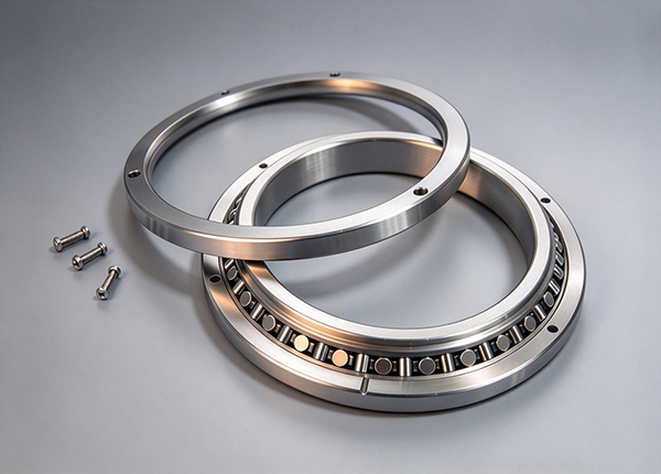
The sections below follow the order we use when an engineer sends us a drawing: inputs first, then a spec table, then selection steps, then mounting, then verification.
Inputs to Collect Before You Request a Bearing
Not every input has to be final on day one. Some block progress and some can be refined after the first quote.
Inputs that block progress
- Error budget for the axis. Write the allowed angular or positional error in arcseconds or microns. Without it, no bearing precision class can be justified.
- Envelope. You need the bore, outer diameter and section height. Section height decides whether you look at a standard crossed roller design or a thin section bearing layout.
- Load case. List the axial load, radial load and overturning moment, even as rough estimates. Moment load is where crossed roller designs differ most from a single-row ball bearing.
- Encoder radius and read-head layout. This tells you how bearing runout turns into angular error (see the worked example below).
Inputs that can wait
- Exact lubricant choice, seal type and final housing material.
- Surface treatment and special mounting holes. We handle OEM changes to dimensions and holes after the base size is fixed.
Comparison: Mapping Metrology Accuracy Targets to Bearing Specs
Use the table to find the row closest to your axis. The runout figures in the P2 row reflect what BY Bearings controls in production: grinding to P2 class with runout held within 1.5 μm. Treat the other rows as selection logic, not guaranteed values. Final numbers come from the drawing review.
| Metrology target | Precision class to request | Runout approach | Rigidity and preload | Friction torque | Mounting tolerance focus |
|---|---|---|---|---|---|
| Fixtures and low-accuracy rotary tables, repeatability in tens of microns | P5 | Check against standard class limits on the drawing | Light preload is usually enough | Rarely the limiting factor | Standard machined seats |
| Vision and optical stages, repeatability in single-digit microns | P4 | Request a measured runout report per lot | Moderate negative clearance to stop wobble under moment load | Specify a torque window, since it affects motor sizing | Seat flatness and bore roundness ground or finish-machined |
| CMM rotary axis, encoder-referenced axes, semiconductor inspection | P2 | Runout within 1.5 μm, 100% inspected before shipment | Tuned preload; high tilting stiffness without extra heat | Low and consistent; matched rolling elements and lubricant | Seat flatness, squareness and housing roundness held to a small fraction of the runout target |
Limit of the table: it assumes a stiff housing. If the housing is thin aluminium or the mating faces are not ground, a P2 bearing will not deliver P2 performance. Pay for the housing before you pay for the next precision class.
Step-by-Step: How to Select Bearings for Inspection Equipment
This is the sequence we follow when we review a drawing for metrology stage bearings or a precision rotary axis bearing.
- Convert the system target into a bearing share. Allocate part of the error budget to the bearing, part to the encoder and part to the housing and drive. A common starting point is to give the bearing no more than about one third. Check: the three shares add up to less than the total with a margin.
- Translate angular error into allowed eccentricity. For a ring encoder read by a single head, angular error in radians is roughly eccentricity divided by encoder radius.
Worked example: a 20 arcsecond target is about 97 µrad. At a 25 mm encoder radius, the allowed eccentricity is about 2.4 μm. A bearing with runout within 1.5 μm leaves roughly 0.9 μm for encoder mounting and housing error. For a 10 arcsecond target on the same radius, the limit drops to about 1.2 μm, so a single head is not enough. Use two opposed read heads or error mapping. - Pick the precision class from the table. If the budget share is under about 2 μm, request P2. If it is a few microns, P4 is usually the better cost point.
- Choose the bearing family by load. For moment-dominated loads with tight section height, review BRE series crossed roller bearings or the BXU and BRU(CRBF) series. For heavy overturning moment with a large table, rotary table bearings are the better family. Send us the housing drawing and we confirm which ring configuration fits your mounting method.
- Set preload and torque targets. State the maximum friction torque the drive can accept. Too little preload gives wobble, and too much raises torque and heat. The heat then shows up as thermal drift in the measurement.
- Write the inspection requirement into the order. Ask for pre-shipment runout and torque data. We inspect 100% of bearings before shipment, so this report is standard practice for us. You can also read how we run quality control.
Mounting Tolerances That Decide Whether the Bearing Performs
A bearing with 1.5 μm runout can behave like a much poorer part once it is bolted down. Thin crossed roller rings take the shape of the surface they sit on.
Common mistakes and what they look like
- Uneven seat flatness. It shows up as a torque that rises and falls once per revolution. Re-lap or regrind the seat.
- Out-of-round housing bore. It shows up as a runout pattern that repeats twice per revolution and disappears when the bearing is removed. Re-bore the housing, and do not shim it.
- Bolt tightening in a circle. It leaves residual distortion. Tighten in a star pattern in three or four increments of torque.
- Mounting the encoder after the bearing without re-centring. This adds eccentricity that no bearing class can remove. Centre the encoder ring on the bearing rotation axis, not on the housing.
- Over-specifying precision for the budget. P2 in a loose structure wastes money. Fix the housing first.
As a starting rule for your drawing, hold seat flatness and housing roundness to about a quarter of the runout target, then confirm with us during review. This is a design guide, not a standard value, and it tightens for the P2 tier.
Completion Check and Recovery
The axis is ready when you can show three results: in-situ runout within your budget share, a steady friction torque through a full turn, and no measurable play under the rated moment load. Measure runout with an indicator at three angular positions after bolting down, not on the bench before assembly.
| Symptom | Likely cause | Step to revisit |
|---|---|---|
| Runout is higher than the bearing report | Housing roundness or seat flatness | Mounting tolerances; re-machine the seat |
| Torque rises as the stage warms | Preload too high or lubricant mismatch | Step 5; request a lower negative clearance |
| Encoder error shows a once-per-turn pattern | Encoder ring off-centre | Step 2; re-centre, or add a second read head |
| Repeatability drifts under tilt load | Insufficient moment stiffness | Step 4; review a larger section or a rotary table family |
Variations That Change the Procedure
Encoder axis bearing accuracy. If the encoder is integral to the bearing assembly, the error budget moves to the ring itself. Ask us for the assembly drawing so we can check ring parallelism.
Large rotary fixtures. Above a certain diameter, the bearing is not the limit. Stiffness of the table decides. Our BRTM series rotary table bearings suit this case.
Automation and handling cells. For compact inspection robots and positioners, see our notes on bearings for the automation industry.
We have supplied crossed roller bearings for semiconductor equipment in Germany and P2 rotary table bearings for gear grinding in Mexico. Both are accuracy-driven axes where mounting accuracy decided the result as much as the bearing grade. We support OEM and ODM changes to dimensions and mounting holes, with no MOQ for engineering samples and trial builds.
Send your error budget, housing drawing and load case, and we will return a bearing proposal with runout and torque targets. Contact the team to get a quote or request selection advice.
 +8618939019135
 sales@bybearings.com
 +8618939019135