Match RB Series Crossed Roller Bearings to Inner Ring Loads
The inner ring turns, the outer ring is bolted into a housing, and the load arrives as a mix of radial force, axial force and tilting moment. How do you pick a size that carries all three without paying for capacity you will never use? This guide answers that for RB Series Crossed Roller Bearings in rotary tables, robot joints and indexing mechanisms. It is written for the specification stage, when the drawing is still open and a wrong size is cheap to fix.
If you are still comparing families, start with our overview of Precision Crossed Roller Bearings. For robot-arm duty, see Bearings for Industrial Robotics.

What Inner-Ring Rotation Changes in a Crossed Roller Bearing
Crossed roller bearings place cylindrical rollers at alternating 90° angles between V-shaped raceways. One bearing can therefore carry radial load, axial load in both directions, and moment load at the same time. That is why a single ring replaces a pair of angular contact bearings in many compact joints.
Which ring rotates matters, because it decides where the load zone sits.
- Inner ring rotating, outer ring fixed: a load that is stationary in the housing frame always presses on the same arc of the outer raceway. The inner raceway sees the load travel around its whole circumference. Housing roundness and stiffness under that fixed zone become the weak point.
- Outer ring rotating, inner ring fixed: the situation reverses. This arrangement suits turntables where the platform is carried by the outer ring, but it changes the fit logic.
Everything below assumes the more common robot-joint and indexing case, with the inner ring on the rotating shaft or hub.
Match Inner-Ring Rotation Arrangements to Combined Loads Step by Step
This is the method we recommend for sizing without over-specifying. Each step lists a checkpoint and the usual way it goes wrong.
- Fix the rotating member and the load frame. Write down which ring turns and whether each load is stationary in the housing frame or rotates with the shaft. Checkpoint: one sketch with the bearing centerline and every force arrow. Common failure: assuming the load rotates with the inner ring when it is actually fixed in the housing. That puts the heaviest contact on one outer-ring arc.
- Reduce every load to the bearing center. You need radial force Fr, axial force Fa and moment M at the bearing's mid-plane. Checkpoint: M equals force multiplied by its offset distance, including payload, tool or arm overhang. Common failure: leaving out the offset of a payload and its acceleration load, which understates M by a wide margin.
- Convert moment into an equivalent radial load. Use Fr + 2M/dp, where dp is the pitch diameter of the roller set. Checkpoint: compare this term with Fa. Common failure: comparing M directly with Fr, which mixes units and hides the fact that moment often dominates.
- Choose the lever that matches the dominant term. Take the load rating values and factors from the catalogue page for your series. Checkpoint: see the table below. Common failure: choosing a thicker section when a larger pitch diameter would do the job.
- Set the precision grade and preload for the function. Positioning axes need tighter running accuracy and negative clearance. Slow rotation with a low torque budget needs a lighter preload. Checkpoint: write the runout and friction torque targets on the drawing. Common failure: asking for the highest grade on a joint that never needs it.
- Check fits, flatness and clamping. With the inner ring rotating and the load moving around it, specify a tighter fit on the inner ring and a locational fit in the housing. Follow the fit table for your bore size. Checkpoint: flatness and squareness of both seating faces. Common failure: uneven clamp bolt torque, which distorts the raceway and shows up as torque ripple.
Which Lever Fits Which Load Pattern
| Dominant load (inner ring rotating) | Right-sized response | Over-specifying trap | When it does not apply |
|---|---|---|---|
| Radial, with small moment and axial load | A single RB bearing at the smallest section that meets the rating | Moving up a section size "for safety" | Shock loads that exceed the rated static load |
| Moment (2M/dp is the largest term) | Increase pitch diameter or the spacing of the load path | A thicker section at the same diameter | Envelope limits that fix the diameter |
| Axial in one direction | Check the axial rating; consider a thrust bearing for pure axial load | Using a crossed roller bearing as a pure thrust element | Axial load combined with real moment |
| Balanced radial, axial and moment | A single crossed roller bearing, since it carries all three in one ring | Two bearings back to back | Long axial spans that need a second support |
| Heavy overturning with dynamic multi-axis load | Move to crossed tapered or rotary table bearings | Stacking more RB bearings | Light loads where RB is already sufficient |
A Worked Example With Illustrative Numbers
These figures are illustrative only and are not from a customer project. A joint carries Fr = 2 kN, Fa = 1 kN and a tilting moment M = 0.5 kN·m on a pitch diameter dp of 0.1 m.
- Moment term: 2M/dp = 2 × 0.5 / 0.1 = 10 kN.
- Radial plus moment term: 2 + 10 = 12 kN.
- The moment alone supplies about 83% of that figure. The axial load of 1 kN is minor.
The decision follows directly. Adding a second bearing or raising the section height would not address the real driver. Raising dp is the efficient route: at the same moment, doubling dp halves the moment-derived term. If the envelope forbids a larger diameter, that is the point where a different type deserves a look. Always check the final rating against the catalogue values for the exact model before you freeze the design.
Common Mistakes That Lead to Over-Specification or Early Wear
- Specifying P2 everywhere. A higher grade costs more and needs better mating surfaces. Reserve P4 or P2 for axes that set positioning accuracy.
- Ignoring housing stiffness. With a fixed outer ring and a stationary load, a thin or uneven housing wastes the bearing's rigidity.
- Treating preload as a fixed value. Heavy preload raises friction torque and heat. Light preload can allow wobble. State the target torque with the runout requirement.
- Skipping the moment calculation. Teams often size on radial load alone because it is the easiest number to find.
- Mounting without checking seat flatness. Distorted raceways cause torque ripple and noise that looks like a bearing defect.
Precision Grade, Runout and Preload by Application
BY Bearings produces P5, P4 and P2 grades, with runout controlled within 1.5 μm and 100% inspection before shipment. Use the grade that fits the axis rather than the highest one available.
| Application | Typical priority | Where to look |
|---|---|---|
| Robot joints and harmonic drive modules | Compact size, low backlash, negative clearance | Bearings for Harmonic Drive |
| Direct drive turntables | Low friction torque, smooth slow rotation | Bearings for DD Motors |
| CNC rotary tables | Tilting stiffness, runout control | Rotary Table Bearings |
| Medical and semiconductor equipment | Low vibration, quiet running | Bearings for Medical Industry |
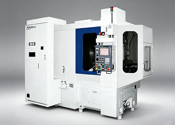
Our precision work includes P2 rotary table bearings supplied to a customer in Mexico for gear grinding, and crossed roller bearings for semiconductor equipment in Germany. Both cases came down to the same point: runout and torque had to be written into the specification, not left to the bearing grade alone. Our Quality Control process uses GCr15 (SAE 52100) steel verified by spectrographic analysis, and metallographic checks after heat treatment confirm hardness in the HRC 60 to 64 range.
When RB Is the Right Fit and When to Choose Another Series
RB bearings cover many compact joints, but they are not the answer to every load case. Use this comparison when the numbers sit near a boundary.
| Series | Best fit | Limit |
|---|---|---|
| RB style crossed roller bearings | Compact joints, indexing, moderate combined loads, inner ring rotation | Heavy overturning or shock loads |
| BRE Series Crossed Roller Bearings | Designs that need a different ring construction | Confirm mounting method against the drawing |
| Crossed Tapered Roller Bearings | High tilting stiffness under dynamic multi-axis load | Larger envelope and higher torque |
| BRTM Series Rotary Table Bearings | Rotary tables with integrated mounting and heavier moments | Not needed for light, compact joints |
| Thin Section Bearings | Light load, very small cross section | Limited moment stiffness |
Buyer's Checklist Before You Send Drawings
- Which ring rotates, and is each load fixed or rotating relative to it?
- Fr, Fa and M at the bearing center, with the offset distances noted.
- Pitch diameter limits and envelope constraints.
- Precision grade (P5, P4 or P2) and a runout target.
- Preload or clearance requirement, plus any friction torque limit.
- Special dimensions or mounting holes that need an OEM or ODM variant.
On the supply side, BY Bearings runs a 13,500 m² intelligent factory with a monthly capacity of 15,000 sets. OEM customization is supported with flexible MOQ, and typical turnaround is 3 to 6 weeks, depending on the specification. Our products carry CE and RoHS certification, and a 12-month warranty runs from the shipment date. Our Germany BBH export business is one example of bulk supply of BBH Series Crossed Roller Bearings.
If you have loads and an envelope but no final size, send your drawing and load data and we will check the selection with you. You can get a quote or ask for selection advice from Daniel Wei's application team at BY Bearings.
 +8618939019135
 sales@bybearings.com
 +8618939019135