Precision Bearings in Harmonic Drives for Industrial Robots: Applications and Challenges
What Are Harmonic Drives and Why Do Industrial Robots Use Them?
A harmonic drive, technically known as strain wave gearing, is a mechanical transmission system invented by C.W. Musser in 1957. Nearly seven decades later, this fundamental principle—using elastic deformation of a flexible spline to achieve high-ratio speed reduction—has become central to the most advanced robots ever built.
The harmonic drive consists of three core components. The wave generator is an elliptical cam fitted with a thin-walled ball bearing. The flexspline is a thin-walled flexible metal cup with external gear teeth machined into its outer surface. The circular spline is a rigid ring with internal teeth, typically two teeth more than the flexspline. When the wave generator rotates, it deforms the flexspline into an elliptical shape, engaging its teeth with the circular spline at two opposite points. Because the flexspline has slightly fewer teeth than the circular spline, each full rotation of the wave generator advances the flexspline by a small angular increment.
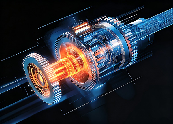
This mechanism achieves reduction ratios typically ranging from 30:1 to 320:1 in a single stage. Unlike planetary gearboxes or cycloidal drives, harmonic drives provide zero backlash without any special adjustment. The gear teeth remain in continuous contact across the entire engagement zone, and the elastic deformation of the flexspline takes up any clearance that would otherwise exist. This produces a transmission with high torsional stiffness and exceptional positioning repeatability—characteristics that are precisely what robotic joints demand.
Harmonic drives are widely used in industrial robot wrist joints, small arm joints, and increasingly in humanoid robots where compact, high-torque actuators are essential. The coaxial input-output configuration means the motor, reducer, and output bearing can share the same axis, enabling the slim, cylindrical joint form factors seen in modern robots. This compact integration is a fundamental enabler of today's robotic architectures, allowing robot designers to pack substantial torque capacity into joints that are barely larger than the motors that drive them.
The harmonic drive's ability to maintain zero backlash over millions of operating cycles is another critical advantage for robotics. In applications such as arc welding, assembly, and inspection, any lost motion at the joint translates directly into positioning error at the tool tip. A robot with even a few arc-minutes of backlash may be unable to perform tasks that require consistent contact force or precise path following.
The Role of Precision Bearings in Harmonic Drive Performance
While the flexspline and circular spline receive most of the attention in harmonic drive discussions, the bearing system plays an equally critical role in determining overall performance. The bearing directly influences the drive's positioning accuracy, rigidity, and operational lifespan.
Two distinct bearing positions exist within a harmonic drive system. The first is the wave generator bearing, a thin-walled flexible ball bearing that sits between the elliptical cam and the inner surface of the flexspline. This bearing must accommodate the continuous elastic deformation of the flexspline while maintaining smooth rotation. Unlike ordinary rolling bearings, the inner and outer rings of this flexible thin-wall bearing are very thin, and when assembled on the oval camshaft, they deform into an elliptical shape. The rolling elements must circulate through regions of varying curvature and stress with every rotation of the wave generator.
The second is the output bearing, which supports the external load acting on the reducer output. This bearing must handle the combined radial, axial, and moment loads transmitted through the robot arm while maintaining the precise positioning that the harmonic drive provides. In most industrial robot harmonic drives, this output position is occupied by a crossed roller bearing.
The distinction between these two bearing positions is essential for understanding harmonic drive design. The wave generator bearing enables the reduction mechanism itself, while the output bearing protects the reducer from external loads and ensures that the precision achieved by the gear mesh is not compromised by bearing deflection. If the output bearing deflects under load, the robot's end effector position will deviate from its commanded position, regardless of how precise the gear mesh may be.
The bearing system also affects the harmonic drive's efficiency. Friction in the wave generator bearing contributes to the drive's no-load running torque, which in turn affects the sizing of the motor and the thermal management requirements of the joint. Minimizing bearing friction without sacrificing rigidity is an ongoing engineering challenge.
Crossed Roller Bearings: The Critical Output Bearing for Harmonic Drives
Crossed roller bearings have become the standard solution for harmonic drive output sections in industrial robots. Their unique structure—cylindrical rollers arranged at 90-degree alternating angles within V-shaped raceways—allows a single bearing to simultaneously withstand axial loads, radial loads, and overturning moments.
This multi-directional load capacity is particularly valuable in robotic joints, where the output must resist forces from multiple directions without introducing deflection that would degrade positioning accuracy. High-stiffness crossed roller bearings are specifically designed to support output loads of harmonic drive units, withstanding high axial and radial forces as well as high tilting moments. The line contact between rollers and raceways provides approximately three times the rigidity of ball bearings of equivalent size.
The crossed roller bearing's compact structure also serves an important secondary function: it reduces subsequent design, production, and assembly costs by removing the need for additional output bearings in many applications. The bearing integrates directly into the harmonic drive housing, creating a self-contained actuator unit that robot designers can mount directly onto the joint structure. This integration simplifies the robot's mechanical architecture and reduces the number of components that must be aligned and preloaded during assembly.
Industry specifications illustrate the performance requirements for these output bearings. High-performance harmonic drive units typically incorporate crossed roller output bearings with accuracy better than 1 arc-minute and repeatability within ±4 to ±10 arc-seconds. These specifications are achieved through precision manufacturing and careful preload control, both of which are essential for maintaining zero backlash in the complete actuator assembly.
The crossed roller bearing also plays a protective role. By handling external loads, it shields the harmonic drive's gear mesh from forces that could otherwise cause uneven tooth loading, accelerated wear, or loss of precision. This protection is critical for maintaining the drive's rated lifespan and consistent performance over millions of operating cycles. In effect, the bearing acts as a mechanical filter, absorbing the complex load patterns generated by robot motion before they reach the sensitive gear interface.
Another advantage of the crossed roller bearing in this application is its ability to be preloaded to zero clearance. The harmonic drive's zero-backlash characteristic depends on maintaining tight contact between the gear teeth. If the output bearing has internal clearance, the output flange can move slightly relative to the input before the bearing engages, introducing backlash into the system that the gear mesh itself does not have. Preloading the crossed roller bearing eliminates this source of error.
Challenges in Harmonic Drive Bearing Applications
Despite their proven effectiveness, precision bearings in harmonic drive applications face several significant engineering challenges.
Flexible Bearing Fatigue and Deformation
The wave generator bearing operates under conditions fundamentally different from conventional rolling bearings. Its thin-walled structure is designed to deform continuously into an elliptical shape as the wave generator rotates. Research on flexible thin-wall bearings has shown that the maximum stress occurs at the major and minor axis positions during operation, with sinusoidal variations in radial displacement and velocity. This cyclic stress pattern places extreme demands on material fatigue resistance.
The bearing's outer ring experiences alternating bending stresses as it passes through the major and minor axes of the elliptical cam. Over millions of cycles, this repeated deformation can lead to fatigue cracking if the material and heat treatment are not properly optimized. The inner ring, which mounts directly to the elliptical cam, experiences a similar but less severe stress pattern.
The vibration characteristics of flexible bearings also differ significantly from ordinary bearings. Even in normal operation, flexible bearings exhibit distinct periodic vibration impacts in their time-domain signals, and their envelope spectra show peaks at even multiples of rotational frequency. This inherent vibration signature complicates fault diagnosis, as it must be distinguished from actual defect signals. A maintenance engineer monitoring vibration on a harmonic drive must understand that some vibration is normal and expected, and that only deviations from the established baseline indicate developing problems.
Friction and Wear in the Wave Generator
The wave generator bearing experiences complex loading as it presses the flexspline into engagement with the circular spline. At the major axis positions, the balls press against the retainer with the largest force, creating concentrated contact stresses. Specialized retainer designs have been developed to address this challenge, with pocket geometries that reduce pressure per unit area at critical positions and decrease wear due to ball-retainer contact.
The lubricant in the wave generator bearing must also withstand the continuous flexing of the bearing rings. Conventional greases may channel or migrate away from the contact zones under this dynamic deformation. Specialized greases with high adhesion and good shear stability are required to maintain adequate lubrication throughout the bearing's service life.
Precision Retention Under Load
For the output crossed roller bearing, the primary challenge is maintaining precision under the complex, multi-directional loads encountered in robotic applications. Deflection in any direction directly translates to positioning error at the robot's end effector. The bearing's preload must be carefully optimized to provide sufficient rigidity without generating excessive friction or heat that would reduce efficiency.
Thermal effects also play a role in precision retention. As the robot operates, heat generated by the motor and the harmonic drive itself causes the bearing components to expand. If the bearing's internal clearance is not properly specified for the expected temperature range, this expansion can either increase preload (causing excessive friction) or reduce preload (allowing backlash to develop). Bearings for harmonic drive applications must be specified with thermal stability in mind.
Space Constraints and Integration
Harmonic drives are selected specifically for their compact form factor. Every component within the drive must contribute to precision and load capacity without adding unnecessary size or weight. The crossed roller bearing's ability to handle multiple load directions in a single unit is a direct response to this constraint, but it also means that any performance limitation in the bearing directly constrains the overall drive capability.
The integration of the output bearing into the harmonic drive housing also creates challenges for assembly and maintenance. In many designs, the bearing is pressed into the housing and retained by the output flange, making replacement difficult without specialized tooling. Designers must balance the benefits of integrated construction against the practicalities of field service and repair.
Lubrication and Contamination
Harmonic drives are often used in environments where contamination is a concern—welding robots produce metal spatter, painting robots produce overspray, and cleanroom robots must avoid particle generation. The output bearing's seals must prevent contaminants from entering the bearing while retaining the lubricant. In some applications, the bearing may need to operate in a vacuum or cleanroom environment, requiring specialized lubricants and sealing materials that do not outgas or generate particles.
Selection Criteria for Harmonic Drive Bearings
Selecting the appropriate bearing for a harmonic drive application requires careful evaluation of several parameters.
Precision Grade
The bearing's runout and rotational accuracy directly affect the harmonic drive's positioning performance. For industrial robot applications, bearings in P5, P4, or P2 precision grades are typically specified, with P2 offering the highest accuracy for the most demanding positioning tasks. Typical high-precision harmonic drive specifications require less than 1 arc-minute accuracy, providing a benchmark for the combined precision of the gear mesh and output bearing.
The precision grade affects both the bearing's cost and its availability. P5 grade bearings are suitable for general industrial applications where positioning tolerances are moderate. P4 grade bearings are used in high-precision robots where consistent accuracy is required. P2 grade bearings are reserved for the most demanding applications, such as semiconductor handling and precision assembly.
Preload Configuration
Preload eliminates internal clearance and enhances rigidity, which is essential for maintaining zero backlash in the complete harmonic drive assembly. The crossed roller bearing's ability to be preloaded during manufacturing or installation allows designers to optimize the trade-off between stiffness and friction. Excessive preload increases running torque and heat generation, while insufficient preload allows deflection under load.
The optimal preload depends on the application's load profile and duty cycle. Robots that experience high moment loads during operation require higher preload to maintain rigidity. Robots that operate at high speeds may benefit from lower preload to reduce heat generation. The bearing manufacturer can provide guidance on preload selection based on the specific application requirements.
Load Capacity
The output crossed roller bearing must be rated to handle the maximum expected axial, radial, and moment loads with an appropriate safety factor. Since the bearing shields the gear mesh from external loads, any overload condition that exceeds the bearing's capacity will ultimately damage the harmonic drive itself.
Load capacity should be evaluated for both static and dynamic conditions. The static load rating determines the maximum load the bearing can withstand without permanent deformation. The dynamic load rating determines the load the bearing can withstand for a specified number of cycles without fatigue failure. Both ratings must be considered in the selection process.
Installation and Integration
Crossed roller bearings designed for harmonic drive output sections typically feature integrated rings with mounting holes, allowing direct bolting to the reducer housing and output flange. This integrated design simplifies assembly and ensures that the bearing's precision is not compromised by the mounting process.
The bearing's mounting interface must be carefully specified to ensure proper alignment with the harmonic drive components. Any misalignment between the bearing and the gear mesh will introduce additional loads and reduce the drive's service life. The bearing manufacturer should provide detailed mounting instructions and tolerances.
BY Bearings: Precision Bearing Solutions for Harmonic Drive Applications
BY Bearings (Luoyang Boying Bearing Co., Ltd.) specializes in the manufacturing of high-precision crossed roller bearings and rotary table bearings for industrial robots, CNC machine tools, and precision automation systems. With over 16 years of industry experience, the company has established itself as a reliable partner for precision motion control applications.
BY Bearings offers a comprehensive portfolio of crossed roller bearings suitable for harmonic drive output applications, including the BRB (RB), BRE (RE), and BRU series. These bearings are available in precision grades up to P2, with every unit undergoing 100% inspection on runout, dimensional accuracy, and rotational torque consistency before shipment.
For harmonic drive manufacturers and robot OEMs, BY Bearings provides customization services including precision grade selection, preload optimization, sealing configurations, and lubrication solutions tailored to specific application requirements. The company's engineering team offers load calculation, model selection, and installation guidance to ensure that bearings are properly matched to each harmonic drive design.
With exports to over 100 countries, BY Bearings delivers reliable solutions for robotics, CNC machining, and precision instrumentation worldwide.
Need precision crossed roller bearings for your harmonic drive application? Contact BY Bearings today for technical consultation and find the optimal bearing solution for your specific requirements.
Frequently Asked Questions About Harmonic Drive Bearings
Q1: Why are crossed roller bearings used in harmonic drive output sections?
Crossed roller bearings handle combined radial, axial, and moment loads within a single unit, which is essential for robotic joints that experience forces from multiple directions. Their compact design integrates directly into the harmonic drive housing, and their high rigidity protects the gear mesh from external loads.
Q2: What is the difference between the wave generator bearing and the output bearing?
The wave generator bearing is a thin-walled flexible ball bearing that deforms elliptically to enable the reduction mechanism itself. The output bearing, typically a crossed roller bearing, supports external loads and maintains positioning precision.
Q3: What precision grade is required for harmonic drive bearings?
Industrial robot applications typically require P5, P4, or P2 precision grades. Typical high-precision harmonic drive specifications require less than 1 arc-minute accuracy and repeatability within ±4 to ±10 arc-seconds, setting a benchmark for combined gear and bearing precision.
Q4: What are the main challenges for bearings in harmonic drives?
The wave generator bearing faces cyclic fatigue from continuous elliptical deformation. The output bearing must maintain precision under complex multi-directional loads. Both must operate within extremely compact spaces while maintaining zero backlash.
Q5: Can BY Bearings provide customized solutions for harmonic drive applications?
Yes. BY Bearings offers custom dimension tailoring, preload optimization, sealing configurations, and lubrication solutions based on equipment structure, load requirements, and installation space. The engineering team works directly with customers to develop bearing solutions that match specific harmonic drive designs.
 +8618939019135
 sales@bybearings.com
 +8618939019135