
Prevent Runout With BBH Crossed Roller Bearing Fits
Is It the Bearing or the Fit? Define the Symptom First
A rotary axis shows repeat-positioning scatter or a visible wobble on the dial indicator, and the bearing gets blamed. Often the bearing is fine. BBH Crossed Roller Bearings are ground to tight geometry, but once they are pressed into a housing and bolted down, the housing and shaft decide how that geometry behaves. This article gives you a diagnosis order, with observable criteria, to tell a fit problem from a bearing problem before you change machining tolerances or buy a replacement.
Keep three things separate while you investigate:
- Observed symptom: what you can measure, such as radial or axial runout, torque that varies per revolution, or positioning that differs between approach directions.
- Suspected cause: a hypothesis, such as an oversize housing bore or a tilted shoulder.
- Confirmed finding: a cause that a repeatable measurement or a physical mark has verified.
Stop condition: if the axis binds, makes grinding noise, or heats up quickly during a hand turn or low-speed run, stop. Running it further can damage the raceways and hide the original cause. Investigate with the axis unpowered.
Preliminary Checks You Can Do Without Dismantling
Start with what costs nothing. Most of these checks fit within a maintenance technician's access.
- Review recent changes. Was the bearing replaced, the housing re-machined, or the mounting bolts re-tightened? A symptom that appeared right after one of these points to the fit or the mounting sequence.
- Check the records. Look for the drawing tolerances on the housing bore, shaft or spigot, shoulder squareness, and flatness. If the drawing has no squareness or cylindricity callout, note that gap.
- Turn the axis by hand, unloaded if possible. Feel for tight spots. Note whether they are fixed to one angular position or travel with the bearing.
- Measure runout at several angular positions. Use a dial indicator on the rotating member, taking readings at multiple points around the circumference (every 90° is a practical start). Record radial and axial values separately.
- Inspect visible surfaces. Look for fretting marks, bright polished patches, or uneven contact on the outer ring, inner ring, and mounting faces.
If the runout pattern is a clean once-per-revolution shape and torque is smooth, suspect eccentricity or tilt. If torque rises and falls with rotation, suspect distortion of the rings.
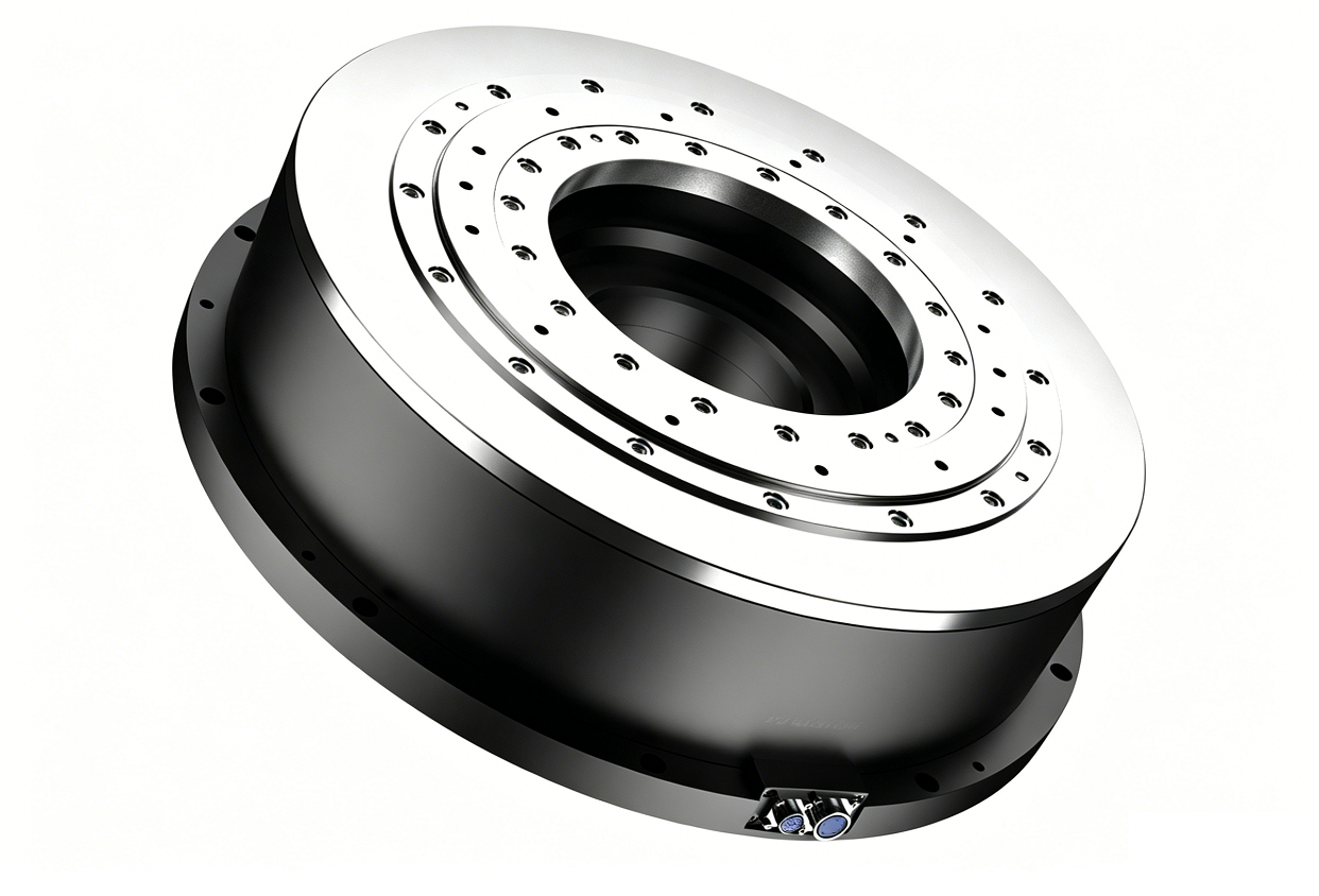
How Housing and Shaft Fit Errors Create Runout, Uneven Preload, and Inconsistent Rotary Accuracy
A crossed roller bearing carries radial, axial, and moment loads in one thin cross-section. That compactness makes the rings flexible compared with a heavy-section bearing. The rings tend to take the shape of whatever they are mounted into, and that shape gets copied into the raceway. The table links each fit error to its mechanism and what you will see.
| Fit or surface error | What happens to the bearing | Observable symptom | First check |
|---|---|---|---|
| Housing bore or shaft seat too loose | Ring is not fully constrained and shifts under load; preload drops | Runout that drifts over time; fretting marks; backlash feel under reversal | Bore and seat diameters against the drawing; look for fretting on the seat |
| Housing bore or shaft seat too tight | Ring is squeezed inward or stretched outward; internal clearance is reduced and preload rises | Higher turning torque, heat at low speed, faster wear | Compare torque before and after mounting; measure bore diameter |
| Out-of-round or lobed bore | The ring conforms to the lobes, so preload varies around the circumference | Torque ripple and runout that repeat at 2 or 3 peaks per revolution | Bore roundness at several depths and angles |
| Shoulder or mounting face not square | Ring is tilted; roller contact shifts to one side of the raceway | Axial (face) runout; one side of the ring shows heavier contact marks | Face runout of the shoulder; contact pattern on the ring face |
| Uneven flatness or uneven bolt tension | Clamping force distorts the rings locally | Torque changes as bolts are tightened; position-dependent accuracy | Re-measure runout after each tightening stage |
| Taper or poor cylindricity on seat | Ring is cocked on its seat; preload differs across the width | Radial runout that differs between measuring planes | Measure the seat at two or more axial positions |
Preload matters here. Crossed roller bearings are often run with slight negative clearance to remove wobble. A fit error moves that setting up or down, so it can undo the design intent. Too much preload means friction and heat. Too little means vibration and poor stiffness. In both cases, rotary accuracy becomes inconsistent from one build to the next. That is a mounting problem, not a bearing defect.
Limits of this table: it does not give fit values. Use the fit recommendation for your specific bearing size and load case, and ask us if the drawing is unclear. A tight fit is not always better; it depends on which ring rotates, the load direction, and the housing material.
Diagnostic Order: Observation, Likely Meaning, Next Action
Work through these branches in order. Each one narrows the cause before you touch the bearing.
| Step | What you observe | What it may mean | Next action |
|---|---|---|---|
| 1 | Runout is high and the peak stays at the same position on the machine when the bearing is turned | Housing or shaft geometry, not the bearing, since the error is fixed to the machine | Measure housing bore and shoulder directly |
| 2 | Runout peak moves with the bearing when you re-mount it rotated by 90° or 180° | A bearing-side or ring-position effect, or a combined stack-up | Re-check the bearing alone on a clean reference; contact us with readings |
| 3 | Runout is low unbolted but rises as bolts are tightened | Mounting-face flatness or uneven clamping | Tighten in stages in a cross pattern; check face flatness |
| 4 | Torque is smooth but high | Overall fit too tight, or preload excess | Verify bore and seat diameters; confirm correct ring position |
| 5 | Torque has 2 or 3 peaks per revolution | Lobed bore or distorted ring | Check bore roundness; consider re-boring or re-honing |
| 6 | Fretting marks, shifting readings between runs | Loose fit or inadequate clamping | Check seat diameters and fastener condition |
Treat each branch as a clue, not a verdict. Two errors can combine. A slightly loose seat plus a tilted shoulder can give a reading that matches neither pattern cleanly. When the evidence does not settle the cause, fix one variable at a time and re-measure.
Escalation point: if housing and shaft measure within the drawing and runout still exceeds your requirement after a clean remount, stop adjusting and send data to support (see the last section).
Mounting Sequence That Protects the Fit
A correct fit can still be ruined by a poor assembly order. This sequence applies to a typical rotary axis, such as a robot joint, indexing table, or industrial robotics joint.
- Clean the housing bore, shoulder, and mounting faces. A single chip under a face acts like a shim and tilts the ring.
- Check seat and bore dimensions against the drawing before fitting, not after.
- Keep the bearing flat and square when seating it. Press on the ring being fitted, never through the rollers or the other ring.
- Seat the ring fully against its shoulder. Confirm with a feeler gauge or by feel that there is no gap.
- Fit the retaining or clamping parts, then tighten bolts gradually in a cross pattern, in at least two stages.
- Turn by hand after each stage. If torque jumps or the feel changes, stop and go back to the table above.
- Take final runout readings at several positions and record them as your baseline.
Where this does not apply: large-diameter units, heated or shrink-fit assemblies, and designs with an integrated flange may need a different method. Check the bearing drawing for those.
Common Mistakes That Create Runout
- Tightening all bolts fully in one pass, in sequence around the circle, so the rings distort.
- Correcting a loose seat with shims or adhesive instead of re-machining it.
- Measuring housing bore at one point only and missing lobing.
- Skipping a baseline reading, so there is nothing to compare after service.
- Assuming a larger fit interference always gives higher accuracy.
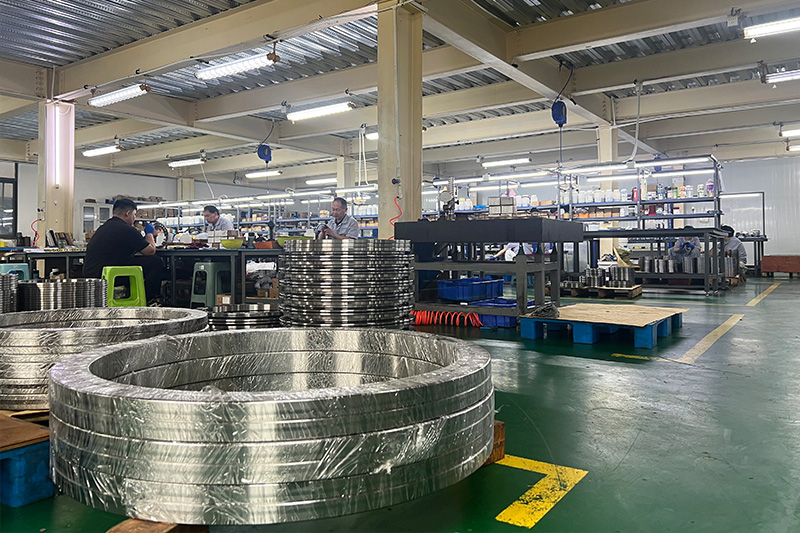
Worked Example: Tracing a Runout Peak
This is an illustrative scenario, not a customer record. A machine builder sees axial runout on a small indexing axis. The peak sits at about the same angle every time. The builder rotates the bearing 180° relative to the housing and re-mounts it. The peak stays at the same machine angle.
That points to the machine side. The builder checks the shoulder face runout and finds that it is not square to the bore axis. Re-grinding the shoulder and re-mounting under staged tightening brings the readings down. The remaining check is whether the new baseline holds after a short running period. If it drifts, the seat may still be loose, and the diagnosis returns to the diameters.
The lesson: change one variable, re-measure, and write down both readings.
Prevention, Records, and When to Contact Support
Most fit-related runout is cheaper to prevent at the drawing stage. Before finalizing machining tolerances, define bore diameter, roundness, shoulder squareness, and face flatness together. Then fix the tightening method in the assembly instruction. Our quality control process includes 100% inspection before shipment, with runout controlled within 1.5 μm. A mounted result worse than that on a shipped bearing therefore points you first to the mounting interface, while a measurement showing the bearing itself is off belongs in a support case.
BY Bearings has supplied precision crossed roller bearings for over 15 years, including BBH crossed roller bearings exported in bulk to a customer in Germany, and P2 rotary table bearings for gear grinding to a customer in Mexico. For heavier overturning loads, see our rotary table bearings and the bearings for machine tools page.
Send this information when you escalate:
- Bearing model, batch or shipment reference, and the date of mounting
- Housing and shaft drawings with measured actual dimensions
- Runout readings at each angular position, before and after tightening
- Torque observations (smooth, peaked, or high) and a note of any fretting
- Photos of the ring faces and mounting surfaces
Our products carry a 12-month warranty from the date of shipment. We assess each case on the evidence, and it may turn out to be either a mounting or a product issue.
If you are still drafting housing and shaft tolerances, send us your drawings and load case and we will review the fit with you. You can get a quote or ask for selection advice through our contact page.
 +8618939019135
 sales@bybearings.com
 +8618939019135

