
Prevent Seal Drag in RU Series Crossed Roller Bearings
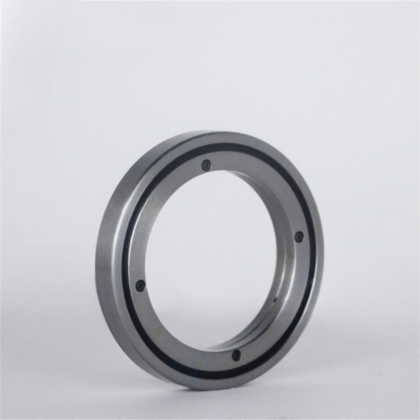
Why does a double sealed bearing turn freely on the bench, then feel tight once it is bolted into the rotary axis? The bearing is rarely the problem. In most cases, RU Series Crossed Roller Bearings in the RU-UU configuration pick up extra torque from the installation: uneven clamping, debris at the seal lip, or a neighbouring part touching the seal. This guide gives assembly engineers a way to find which of these is happening, and a sequence that prevents it before production starts.
What You Will Achieve and Where You Start
The goal is an installed RU-UU bearing whose starting torque stays close to the free torque you measured before mounting. It should also feel the same at every angular position. You are starting with a bearing still in its packaging, a prepared housing or shaft interface, and an assembly procedure that is not yet released.
Some seal drag is by design. Contact seals touch the opposing ring, and that contact adds a baseline torque. This guide deals with the extra torque, the part that appears only after mounting. That is the part you can remove.
Inputs and Tools Needed Before You Open the Box
Some items block the start of work. Others can be settled later. Sort them first.
| Item | Why it matters | Blocks progress? |
|---|---|---|
| Mounting drawing with flatness and bolt torque limits for the bearing model | Clamping distortion is the most common source of excess torque. You cannot judge it without the limits. | Yes. Request it from BY Bearings if you do not have it. |
| Low speed torque gauge, or a spring scale on a known radius arm | You need a number for before and after, not a feel by hand. | Yes |
| Calibrated torque wrench or torque screwdriver | Uneven bolt load deforms the thin rings. | Yes |
| Dial indicator and straightedge | Checks mounting face flatness and coaxiality. | Yes for first articles |
| Lint free wipes and a clean bench | Debris at the seal lip raises torque and shortens seal life. | Yes |
| Relubrication interval and grease top-up plan | Matters for service, not for the first installation check. | No. Can be settled later. |
Installation Sequence With Checkpoints
Measure free torque on the bench. Place the bearing on a clean, flat surface or a simple fixture. Rotate it slowly and record the starting torque and the running torque. This is your reference. If you skip it, every later reading is a guess.
Prepare the mating surfaces. Wipe the shaft, housing, and bolt faces, not the seal lips. Remove burrs from hole edges and corners. Check the mounting faces with a straightedge or dial indicator against the flatness limit on the drawing. A raised burr under a thin ring pulls the ring out of round when bolts are tightened.
Check clearance around the seals. Confirm that covers, spacers, and labyrinth parts leave a gap at the seal faces. Any part that touches a seal turns a light seal contact into a heavy one.
Seat the bearing squarely. Bring it onto its pilot diameters by hand or with even, distributed pressure. Never hammer on a ring edge or press on a seal. If the bearing needs force to enter, stop and check the fit and the squareness of the pilot.
Tighten bolts in a star pattern, in stages. Start with all bolts finger tight, then bring them up in increments to the drawing value. Rotate the bearing by hand after each stage. What good looks like: torque stays steady stage by stage. Typical mistake: tightening one bolt to full value and working around the circle. That locks in a distorted ring.
Fit the mating component and re-check. Bolt up the rotating part, then check coaxiality and face runout with the dial indicator. Misalignment here loads the bearing sideways and pushes the seals against their counter faces.
Measure starting torque again. Take the same reading with the same fixture and the same method. Compare it with step 1.
How Clamping, Contamination and Seal Contact Raise Starting Torque in RU-UU Designs
RU bearings use integral inner and outer rings with thin cross sections, so they follow whatever shape the mounting faces give them. Add two contact seals and you have three places where installation can add torque. The table lists each cause, the symptom you will see, and the check that confirms it.
| Condition | What happens inside | What you observe | How to confirm | Recovery |
|---|---|---|---|---|
| Uneven bolt tightening | Ring is pulled out of round, so rollers load unevenly and seal lips press harder on one side | Torque rises as bolts reach final value, with tight and loose spots around the circle | Loosen all bolts. If torque drops to near bench value, clamping is the cause. | Re-tighten in a star pattern, in stages |
| Non flat or burred mounting face | Ring conforms to the high spot and stays distorted | Same angular position is tight every time | Dial indicator or straightedge on the face; mark the tight angle | Rework the face, remove burrs, re-seat |
| Neighbouring part touches a seal | Seal lip is squeezed beyond its design contact | Torque stays high at all angles, sometimes with light rubbing sound | Feeler gauge at covers and spacers; look for polished marks on the seal | Restore the gap; replace the part if it is out of drawing |
| Debris at the seal lip | Particles hold the lip against the ring or scratch the counter face | Rough, uneven torque with stick slip at low speed | Inspect lip under light; check for swarf, dust, or cured sealant | Remove, clean the area, and replace the bearing if the lip or raceway is marked |
| Excess grease or sealant near the seal | Adds viscous drag and can migrate onto the lip | High torque that eases as the unit warms or after several turns | Compare cold and warm torque; look for squeezed-out material | Remove surplus. Never remove the seal to free the bearing. |
| Housing and shaft not coaxial | Bearing is forced to run off axis, loading rollers and seals unevenly | Torque varies with angle; runout reading is high | Dial indicator on the rotating part | Re-align at the mounting interface |
Limits of this table. It assumes the bearing was within its torque range on the bench. If the bench torque in step 1 was already high, the issue is the bearing or its seals, not the installation. In that case contact the supplier with your reading. Do not try to correct it in assembly.
Common Mistakes That Create Seal Drag
Judging torque by hand only. Two operators will give two answers. Use a gauge and record the number.
Cleaning the seal with solvent. Wipe the surrounding faces. Soaking a seal can leave residue on the lip and does nothing for the raceway.
Applying sealant close to the bearing. Uncured material reaches the lip and cures there.
Removing a seal to lower torque. The torque drops and the bearing is then open to contamination. The real cause stays in the installation.
Using the same bolt torque for different bearing sizes. The limit is on the drawing for each model. Check it every time.
Completion Check and Recovery
Treat the installation as finished when all of the following are true:
Starting torque after final tightening sits close to the free torque recorded in step 1, with no sharp rise at any angle.
Rotation through a full turn is smooth, without stick slip or rubbing noise.
Face and radial runout of the rotating part is within the drawing limit.
No grease, sealant, or debris is visible at the seal lips.
After a short run in, the housing near the bearing has not warmed noticeably.
If a check fails, go back in this order. First loosen all bolts and measure torque. If it falls, the cause is clamping or mounting face flatness, so return to steps 2 and 5. If it stays high, look for contact at covers and spacers (step 3), then debris (step 2). If torque is only high at one angle, check coaxiality and face runout (step 6). A small drop in torque over the first few rotations is normal as grease spreads. A reading that stays high or climbs is not.
For reference, every BY Bearings crossed roller bearing is inspected 100% before shipment, with runout controlled within 1.5 μm. We apply the same inspection to crossed roller bearings supplied for semiconductor equipment in Germany. Our Quality Control page describes the process. If your bench reading in step 1 is unclear, send it to us along with the bearing model for review.
Where the Procedure Changes
Only a few conditions change the steps above.
Robot joints and compact axes. Housings are thin and may deform more under bolt load. Use more torque stages and measure after each one. See our Bearings for Industrial Robotics page for how these bearings are applied.
High accuracy rotary tables. When the axis uses P2 grade bearings, such as the P2 Rotary Table Bearings we supplied to a gear grinding customer in Mexico, face flatness and coaxiality matter more because the bearing itself adds almost no error. Check them with a dial indicator on every unit.
Special mounting holes or dimensions. If your housing does not match the standard layout, we support OEM customization of dimensions and mounting holes. Settle this before assembly, not after trial fitting.
Other series. If your axis does not need integral rings with seals, look at Precision Crossed Roller Bearings in other designs. Seal checks do not apply to open types, but the clamping and flatness steps still do.
Next Step
Before your assembly procedure is released, send BY Bearings the bearing model, the housing and shaft drawing, and your target starting torque. Our engineers will review the mounting faces and seal clearances with you, or you can get a quote for RU-UU bearings built to your drawing.
 +8618939019135
 sales@bybearings.com
 +8618939019135

