
RU Series Crossed Roller Bearings Mounting
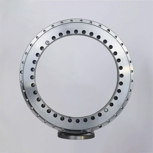
Machine designers often ask one practical question during early axis design: can the bearing itself reduce the number of housings, flanges, and retaining parts required around a rotating joint? RU Series Crossed Roller Bearings are designed for this purpose. Their inner and outer rings include mounting holes, allowing each ring to be bolted directly to its mating component.
This arrangement changes more than assembly time. It affects the load path, machining plan, tolerance stack, service access, and total space required around the axis. For designers comparing bearing concepts, Precision Crossed Roller Bearings can provide a compact answer where radial load, axial load, and overturning moment act together.
BY Bearings supplies crossed roller bearings, harmonic drive bearings, crossed tapered roller bearings, rotary table bearings, slew bearings, thin section bearings, spherical roller bearings, cylindrical roller bearings, and thrust bearings for industrial motion systems. With more than 15 years of precision bearing manufacturing experience, we support OEM and ODM projects where mounting geometry must be reviewed alongside bearing accuracy and load requirements.
Start with the mounting architecture rather than the bearing diameter
A conventional bearing arrangement often requires several surrounding parts: a housing bore to locate one ring, a shaft shoulder to locate the other, one or two retaining flanges, fasteners, and sometimes spacer rings. Each part adds machining operations and introduces another opportunity for axial or radial misalignment.
The RU configuration takes a different approach. Both rings are manufactured as rigid rings with mounting holes. The designer can connect the outer ring directly to a stationary base and the inner ring directly to a rotating table, arm, or output member. The bearing becomes part of the structural interface rather than a component hidden inside a separate housing.
This approach fits best when the machine needs a short axial stack, high tilting stiffness, and a clear method of attaching components on both sides of the bearing. Typical examples include robot joints, compact rotary tables, indexing mechanisms, semiconductor handling equipment, medical positioning units, and direct drive axes.
| Design question | Direct ring mounting effect | What to verify early |
|---|---|---|
| How is the outer ring retained? | It can bolt directly to a fixed support structure. | Confirm the support face is flat, clean, and sufficiently rigid. |
| How is the inner ring retained? | It can bolt directly to the rotating member. | Confirm bolt access after the drive, encoder, or cover is installed. |
| Where is radial location controlled? | The bearing rings and prepared mounting surfaces establish the assembly location. | Define locating features and runout requirements in the drawing. |
| Can a flange be removed? | Often yes, because the bolted ring performs the retention function. | Check whether the removed flange also served another structural or sealing role. |
| Can the axis be shortened? | Often yes, because shoulders, retainers, and spacer parts may be reduced. | Review motor, seal, cable, and encoder clearances before finalizing the stack. |
The conclusion is straightforward: choose direct ring mounting when reducing surrounding parts improves the machine layout without weakening the supporting members. It does not suit every design. If the support structure is thin, poorly accessible, or unable to hold accurate mounting faces, a conventional housed arrangement may be easier to control.
How mounting holes in both rings remove separate flange and housing requirements while preserving installation accuracy
The main differentiator is not simply that the rings have holes. It is how those holes allow the rings to be fixed directly to two prepared machine members. One ring attaches to the stationary side and the other attaches to the moving side. This removes the usual need for a separate retaining flange and can remove the need for a dedicated bearing housing bore as the primary retention method.
A support structure is still required. The bearing must be mounted to sufficiently rigid, machined faces. What changes is the architecture: instead of making a housing to capture a bearing and then adding flanges to hold it in place, the machine structure becomes the direct interface for the bearing rings.
| Mounting feature | What it replaces or reduces | Practical benefit | Limit of the benefit |
|---|---|---|---|
| Outer ring mounting holes | Separate outer ring retaining flange | Fewer parts and easier direct attachment to a base plate or frame | The fixed support must provide a flat, rigid mounting face |
| Inner ring mounting holes | Separate shaft shoulder and clamping arrangement in many layouts | Direct connection to a rotary table, arm, or drive output | The rotating member must provide tool access for tightening screws |
| Prepared ring faces | Excess reliance on a deep housing bore for alignment | Location can be controlled through the mating faces and defined locating features | Face errors transfer directly into rotational error |
| Bolted ring connection | Multiple retention components | Shorter axial package and a clearer load path | Fastener selection and tightening sequence must be engineered |
Installation accuracy is preserved when the mating surfaces control the ring position consistently and the bolts clamp the rings without distorting them. The mounting holes do not automatically create precision. Precision comes from the combination of bearing geometry, face quality, correct seating, suitable screw tightening, and an assembly sequence that prevents one side from being pulled down unevenly.
For example, if one mounting face has local burrs, paint overspray, trapped chips, or a raised screw head, the ring may tilt when tightened. In a rotary axis, that tilt can appear as face runout, torque variation, or unstable positioning. The solution is not simply to apply higher torque. Remove the cause, inspect the contact faces, and reassemble using an even tightening pattern.
For applications with a heavy overturning moment, direct ring mounting can be especially useful because the load transfers through broad ring faces into the structure. However, do not assume that every thin plate is acceptable. If the table or frame deflects, the bearing may be forced out of its intended geometry. In that case, increase structural stiffness or reconsider the bearing arrangement.
Specify the support faces and bolt pattern before releasing the machine drawing
A direct mount bearing should be selected together with its mating structure. Waiting until late in the project creates avoidable changes to hole locations, tool access, motor offsets, and cover geometry. The best approach is to place the bearing outline, mounting pattern, load direction, and assembly access into the early rotary axis design.
Use the bearing drawing as an interface document
Request the dimensional drawing before finalizing the surrounding parts. Check the inner and outer ring mounting holes, the available screw engagement, the clearance needed for assembly tools, and the location of any lubrication or sealing features. For a compact automation joint, the ability to reach all screws may decide whether the assembly is practical on the production line.
Define what locates the rings
Bolts primarily clamp parts together. They should not be treated as the only answer for repeated radial location where high positioning accuracy is required. Depending on the machine design, use controlled mounting faces and suitable locating geometry to establish repeatable position. The exact locating method should match the required accuracy, manufacturing process, and service plan.
BY Bearings can support flexible customization for special dimensions and mounting requirements. This is useful when standard mounting holes conflict with cable passages, motor adapters, or a customer’s established bolt pattern. The limit is equally clear: customization should begin before production, with complete interface drawings and the application load information.
Protect the load path
Crossed roller arrangements are selected because they can carry combined loads in a compact envelope. Yet the surrounding structure must transmit those loads evenly. A cantilevered rotary plate, for example, creates a large overturning moment at the bearing. If the plate is too flexible, bearing performance can be limited by the structure rather than by the bearing itself.
For machine tool applications, consider whether the axis sees intermittent cutting loads, continuous torque, or frequent indexing. Designers working on turn mill or rotary equipment can also review Rotary Table Bearings when the application requires a bearing family developed around table duty and multi direction loading.
Choose accuracy and preload based on the real motion requirement
Mounting convenience should not be the only selection criterion. The bearing must still meet the accuracy, stiffness, friction torque, load, and speed needs of the machine. A compact assembly that is easy to bolt together is not a good result if it produces unwanted motion error under load.
| Parameter | What it affects in practice | If selected too low or too loose | When a higher requirement makes sense |
|---|---|---|---|
| Accuracy class | Rotational accuracy and repeatable axis behavior | Runout or positioning variation may exceed machine targets | Precision measurement, grinding, wafer handling, and high accuracy rotary systems |
| Preload condition | Rigidity, internal clearance, and starting torque | Excess motion can appear under reversing or moment loads | Axes where backlash control and stable positioning matter |
| Ring size | Load capacity, stiffness, mounting envelope, and inertia | A small bearing may have insufficient stiffness for the supported structure | Large tables, long arms, or high overturning moments |
| Mounting structure stiffness | How evenly the bearing is supported during operation | Distortion can increase torque variation and reduce accuracy | Heavy loads, intermittent shock, and high accuracy rotation |
As a practical rule, use the lowest accuracy and preload condition that still meets the machine requirement. This controls cost and avoids unnecessary friction. Do not apply this rule where micro motion, repeat positioning, or surface finish is directly tied to axis error. There, the bearing selection must be assessed together with the drive, feedback device, and structural deflection.
BY Bearings controls runout within 1.5 μm and performs 100% inspection before shipment under its ISO 9001 quality system. These controls are relevant for customers whose drawings call for close rotational performance, but the final installed result still depends on the customer’s mounting faces and assembly method.
For equipment needing a different geometry or load arrangement, Crossed Tapered Roller Bearings may be considered during concept selection. They should not be substituted only because they look similar on a layout drawing; compare the actual mounting method, loads, stiffness target, and available assembly space.
A practical installation procedure for direct ring mounting
The following procedure helps protect precision bearing installation. It is a general process; always follow the approved drawing, fastener specification, and assembly instructions for the selected part.
- Inspect both mounting faces. Remove burrs, chips, oil residue, paint, and raised material. Check that the faces are clean and undamaged before the bearing is placed.
- Confirm component orientation. Identify the fixed member, rotating member, load direction, and screw access. Verify that no cover, coupling, or motor component blocks a required fastener.
- Support the bearing evenly. Place it carefully on the prepared face. Do not allow one edge to carry the full ring weight during assembly.
- Install screws loosely first. Start all accessible screws by hand so the ring can settle against the face without being pulled down at one point.
- Tighten in a cross pattern. Increase tightening gradually and evenly around the circumference. This reduces the risk of local ring distortion.
- Mount the opposite ring. Repeat the controlled tightening sequence after confirming that the rotating member sits correctly against the bearing face.
- Check rotation by hand. Look for binding, abnormal torque change, contact with adjacent parts, or inconsistent feel through a full rotation.
- Verify the finished axis. Measure the characteristics required by the machine drawing, such as rotational runout or axial motion, before final covers and drive parts are installed.
This process is best suited to precision assemblies where direct access is available. It does not replace a controlled work instruction for high volume production. Where the bearing is buried behind a motor or enclosed in a tight robot wrist, redesigning access points may save more assembly time than changing the bearing itself.
Avoid the common design mistakes that erase the mounting advantage
- Using mounting screws as locating pins: Screws provide clamping force, but relying on clearance holes alone for high accuracy location can create variation. Define a repeatable locating strategy where the application demands it.
- Ignoring support face stiffness: A bearing can be accurately made yet perform poorly if a thin plate bends beneath it. Strengthen the interface when moment loading is significant.
- Removing flanges without reviewing secondary functions: A flange may also support a seal, guard, sensor target, or cover. Replace those functions intentionally rather than discovering the omission during assembly.
- Blocking screw access: Early CAD layouts can look correct while leaving no room for a torque tool. Check the full assembly sequence, not only the final assembled model.
- Over specifying precision: Higher accuracy can be appropriate, but it should be justified by the complete system requirement. A flexible structure or low resolution feedback system may not benefit from a tighter bearing specification.
- Ignoring service removal: Direct mounting simplifies initial assembly, but the machine should also allow removal if inspection or replacement is required.
A useful worked scenario is a compact rotary inspection table. The stationary base supports the outer ring, while the rotating platen bolts to the inner ring. Direct ring mounting can reduce the need for separate retention parts and shorten the stack height. However, if the platen includes an offset workpiece fixture, the engineer must calculate the resulting overturning moment and confirm that both the bearing and platen stiffness are suitable. The direct mount concept helps packaging; it does not remove the need for load analysis.
Use an early selection checklist before requesting a bearing drawing
Before contacting a supplier, prepare the information below. It allows the bearing supplier to assess whether the direct mount concept fits the machine instead of only matching an outside diameter.
- Required inner diameter, outer diameter, and allowable axial space
- Radial, axial, and overturning moment loads
- Rotation speed, duty cycle, and motion pattern
- Required rotational accuracy and allowable runout
- Preferred mounting hole arrangement and available screw access
- Material and stiffness of the fixed and rotating support members
- Environmental conditions, lubrication needs, and sealing arrangement
- Required quantity, prototype timing, and any OEM drawing requirements
Provide those details with the machine interface drawing. BY Bearings can then recommend a suitable crossed roller bearing arrangement, assess mounting feasibility, and discuss customization where standard ring geometry does not match the design. For a project that needs direct mounting and controlled rotational performance, send your drawing to get a quote and request selection advice.
 +8618939019135
 sales@bybearings.com
 +8618939019135

