
BRT Rotary Table Bearings and Indexing Accuracy
When a rotary axis misses its commanded position, engineers often ask whether the bearing is the limiting component or whether the surrounding table structure is responsible. The answer depends on which error is being measured. BRT Rotary Table Bearings can influence rotary table accuracy through runout, internal axial and radial movement, stiffness, friction torque, and preload behavior. However, even a high-precision bearing cannot correct an inaccurate mounting shoulder, distorted housing, poor encoder reference, or unstable clamping system.
For machine-tool and automation designers, the practical task is to separate bearing-related motion from assembly-related motion before setting a bearing grade or tightening production tolerances. BY Bearings supplies Rotary Table Bearings for rotary axes, along with crossed roller bearings, harmonic drive bearings, crossed tapered roller bearings, slew bearings, thin section bearings, spherical roller bearings, cylindrical roller bearings, and thrust bearings. This product range supports applications where radial load, axial load, overturning moment, and positioning repeatability must be considered together.
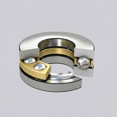
The bearing should be treated as one part of an accuracy chain. Its geometry and stiffness establish a base for motion quality, while mounting geometry and feedback determine whether that base can be realized in the finished machine. For high-precision projects, BY Bearings can provide P5, P4, and P2 precision levels. Our grinding process can reach P2 class, with runout control within 1.5 μm and 100% inspection before shipment. Those controls verify the bearing component; they do not replace verification of the complete rotary assembly.
Start by separating positioning accuracy from repeatability
Indexing accuracy and repeatability are related but different. Confusing them can lead to the wrong corrective action.
| Measurement | What it describes | Likely bearing influence | Other common contributors |
|---|---|---|---|
| Positioning accuracy | Difference between commanded angle and actual angle | Variable friction, elastic deflection, and internal movement can affect it under changing load. | Encoder calibration, drive transmission error, controller compensation, thermal growth, and clamping behavior. |
| Repeatability | Ability to return to the same angular position repeatedly | Stable preload and consistent torque support repeatable movement. | Servo tuning, lubricant condition, cable forces, motor response, and measurement method. |
| Axial face runout | Wobble of the rotating table face during revolution | Bearing axial runout contributes directly. | Table face flatness, mounting shoulder condition, bolt tightening sequence, and contamination. |
| Radial runout | Radial displacement of a rotating pilot or fixture | Radial bearing geometry and internal clearance contribute. | Housing bore form, shaft form, fixture concentricity, and load direction. |
Conclusion: Choose bearing precision based on the motion variable that limits the process, not simply on the smallest available tolerance. A gear grinding table may require strict face runout and tilting stiffness because the workpiece position changes under cutting force. A light inspection turntable may place more emphasis on low, stable friction torque and encoder feedback. The same bearing grade is not automatically appropriate for both systems.
This distinction also explains why a rotary axis can show good unloaded repeatability yet lose indexing quality during machining. Under load, the table, housing, and bearing act as one elastic system. If moment stiffness is insufficient, the axis can deflect even when encoder feedback indicates that the motor reached its commanded position.
Compare bearing runout, axial radial play, and mounting surface error
These three conditions are often grouped together as “table wobble.” They are not interchangeable. Each has a different physical source, measurement method, and corrective action. Treating all three as a bearing problem can result in unnecessary bearing upgrades while the true assembly error remains unchanged.
| Error source | What it affects | How it appears during indexing | Best verification method | When bearing selection helps |
|---|---|---|---|---|
| Bearing runout | Rotating face or pilot motion caused by bearing geometry | A repeatable cyclic variation as the table rotates | Measure the relevant table surface with a dial indicator while rotating under defined mounting and load conditions. | When the measured pattern follows rotation and the mounting surfaces have been verified. |
| Axial radial play | Relative movement between bearing rings under reversing axial, radial, or moment load | Position shift when load direction changes, especially between approach directions | Apply controlled load reversals and measure displacement at the workholding point. | When load reversal exposes clearance or insufficient preload in the bearing arrangement. |
| Mounting surface error | Ring distortion caused by uneven shoulders, bore form error, contamination, or bolt loading | Runout may increase after installation and may not match the bearing inspection result | Inspect shoulder flatness, perpendicularity, cleanliness, bolt pattern, and tightening sequence before bearing installation. | It does not. Correct the mounting interfaces first. |
Key conclusion: Bearing runout is a geometric characteristic of the bearing, axial radial play is load-dependent relative movement, and mounting surface error is an installation-induced distortion source. They can occur together, but they require separate checks.
A common misunderstanding is to request a tighter runout requirement after observing angular positioning error. That request fits only when runout is actually affecting the measured feature. For example, a dial indicator reading on a table face may show axial motion, but it does not directly identify encoder scale error or drive compliance. Conversely, a machine may index poorly under an overturning moment while face runout remains low. In that case, stiffness and preload behavior deserve attention before tighter geometric runout is specified.
How the three sources interact
Runout plus a long workholding offset: Small face motion can become more visible at a fixture located farther from the bearing centerline. This matters for tall parts, grinding fixtures, and measurement probes.
Axial radial play plus reversing load: A table can settle differently when cutting force or workpiece mass changes direction. The effect may be absent during a light no-load index test.
Mounting error plus high preload: Higher preload can improve resistance to relative movement, but it also makes the system more sensitive to distorted mounting surfaces and can increase friction torque.
Surface contamination plus bolt tightening: A particle under a ring support face can locally tilt or deform the ring. No precision class can compensate for this installation condition.
The practical limit is clear: specify a tighter bearing only after the loading condition, mounting interfaces, and measurement target are defined. For a rotary axis used in heavy milling, the relevant target may be workpiece tilt under moment load. For a compact direct-drive inspection stage, low torque variation and fine rotational smoothness may carry more weight.
Understand how preload and stiffness affect an indexed position
Rotary table bearings carry combined loads. A typical application imposes axial load from the table and workpiece, radial load from off-center fixtures, and an overturning moment from cutting force or an elevated center of gravity. The bearing arrangement must resist these loads while maintaining controlled relative motion between rings.
Preload removes or reduces internal free movement by establishing contact conditions before external loading occurs. This can improve rotary axis stiffness and support more stable indexing under load reversal. It is especially relevant for machining tables, turn-mill axes, and automation joints where wobble can affect tool position or part alignment.
There is a trade-off. More preload is not simply “more accurate.” Increased preload can raise friction torque and heat generation. It can also magnify the effect of poor mounting geometry. A design with high preload but weak housing support may still lose accuracy because the housing deflects. Select preload only after evaluating the operating load, rotational speed, thermal condition, drive torque, and required motion smoothness.
For applications that experience large overturning moments, consider whether a rotary table bearing or a Crossed Tapered Roller Bearings arrangement better matches the structural load path. The decision should not be based on nominal load alone. The location of the load, the table diameter, structural stiffness, and required indexing behavior all affect the result.
For compact axes where radial, axial, and moment loads must be carried in one bearing position, Precision Crossed Roller Bearings may also be evaluated. They are particularly relevant when installation space is limited and the assembly requires high rigidity. They are not a direct replacement in every rotary-table layout; mounting dimensions, load direction, lubrication arrangement, and table structure still need review.
Use a verification sequence before changing the bearing specification
Engineers should test the completed rotary assembly in an order that prevents false conclusions. The following sequence helps identify whether the bearing, mounting arrangement, or control system governs indexing performance.
Define the measured output. State whether the target is angular position, face runout, pilot concentricity, workpiece tilt, or repeatability at a tooling point. These are different acceptance targets.
Record the load condition. Test unloaded and under representative axial, radial, and moment loading. A no-load result alone cannot represent machining behavior.
Check mounting interfaces. Inspect support shoulders, bore and shaft seating surfaces, cleanliness, and bolt tightening sequence. Correct visible interface issues before changing the bearing grade.
Measure runout at relevant locations. Check the rotating table face, central pilot, and workholding location where practical. Compare the pattern through a full revolution.
Test both indexing directions. Approach positions from clockwise and counterclockwise directions. A directional difference points toward clearance, transmission compliance, servo behavior, or load-dependent settling.
Test with load reversal. Apply representative force directions and observe whether the table shifts. This identifies whether axial radial play or structural flexibility is influencing the result.
Review torque and thermal behavior. If motion becomes less consistent after operating time, inspect friction torque, lubricant choice, preload, and thermal expansion effects.
Then request bearing data. Provide drawings, load cases, speed, target measurement, and mounting details so the supplier can recommend a suitable accuracy level and arrangement.
This sequence fits early design work because it identifies where tighter tolerances produce value. It does not replace a full machine acceptance procedure, particularly where encoder calibration, servo compensation, hydraulic clamping, or process forces are major sources of error.
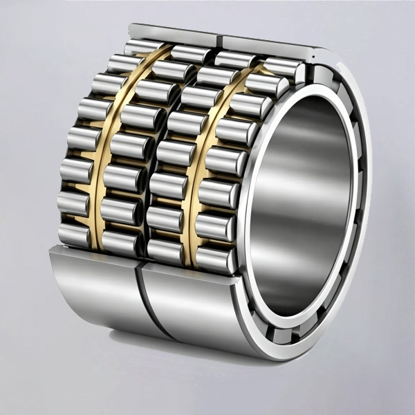
Apply the analysis to gear grinding and precision machining tables
A useful application example is a rotary table used for gear grinding. The table must hold the workpiece in a stable angular relationship while process forces act on the system. If a design team observes surface pattern variation or indexing inconsistency, it should not assume that angular encoder resolution is the sole answer.
First, inspect axial face motion and workpiece tilt under representative loading. Next, compare behavior during opposite index approaches. If the result changes when force direction changes, investigate preload, axial radial play, support stiffness, and fixture location. If the variation repeats at the same rotational positions without a load-direction effect, inspect bearing runout and mounting-surface condition. If mechanical measurements are stable while command-to-position error remains, investigate the feedback and drive system.
BY Bearings has supplied P2 rotary table bearings for a gear grinding application in Mexico. This case supports the relevance of high precision bearing selection for this type of process, but it should not be interpreted as a universal specification for every grinding table. Bearing size, workpiece mass, table structure, mounting accuracy, and the customer’s final acceptance target must be assessed separately.
Our 15+ years of precision bearing manufacturing experience informs this application-focused approach. Rather than selecting only by catalog dimensions, we recommend defining the complete load and accuracy chain. For machine-tool projects, our Bearings for Machine Tools application support can help engineers compare rotary-axis requirements with the bearing arrangement and installation method.
Use this design checklist when setting a bearing requirement
Specify the accuracy target: Identify whether the drawing controls angular position, face runout, radial runout, workpiece tilt, or return repeatability.
State the loading condition: Include axial load, radial load, overturning moment, and the distance from the bearing centerline to the working point.
Define the mounting concept: Show locating shoulders, fits, bolt positions, table face, housing support, and lubrication arrangement.
Set a realistic precision level: P5, P4, or P2 should be selected according to the required machine output and verified assembly capability.
Request inspection information: Confirm which runout characteristic is inspected, how it is measured, and whether the requested value applies to the bearing component or the assembled table.
Evaluate torque requirements: Confirm that the drive can handle the friction torque associated with the selected preload and operating condition.
Plan assembly controls: Include cleanliness, mounting shoulder inspection, bolt tightening method, and post-installation runout verification in the build procedure.
The best bearing decision is therefore not “choose the highest grade.” It is “choose the grade and preload that match the verified accuracy limit of the complete axis.” A P2-class bearing may be appropriate where the machine structure, mounting surfaces, inspection method, and process requirement can use that precision. Where housing or table distortion dominates, improving those parts first may produce a larger gain.
Send BY Bearings your rotary table drawing, load conditions, and indexing target to get a quote and selection advice.
 +8618939019135
 sales@bybearings.com
 +8618939019135

