Crossed Roller Bearings: When Compact Design Pays Off
Why One Bearing Can Be Better Than Two for Complex Loads
Engineers often face a difficult trade-off: designing a compact machine while ensuring it can handle complex, multi-directional loads without compromising rigidity. Traditionally, this required two separate bearings—one for axial loads and one for radial loads—consuming valuable space and increasing assembly complexity. This is the specific design challenge where the unique architecture of Precision Crossed Roller Bearings provides a direct solution.
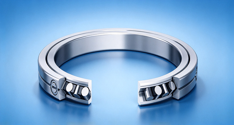
Unlike standard bearings, these components integrate two sets of raceways and rollers within a single unit. The cylindrical rollers are arranged at a 90-degree angle to each other, with their axes of rotation alternating. This configuration allows a single bearing to simultaneously manage:
Radial loads
Axial loads (in both directions)
Overturning moment loads
This single-component approach immediately reduces the axial space required for the bearing assembly. It simplifies the surrounding housing and shaft design, leading to a lighter, more compact, and often more rigid final product. For applications like robotics, CNC rotary tables, and medical imaging systems where space is at a premium and high positioning accuracy is non-negotiable, this consolidation is a significant advantage.

Application Boundaries: When to Choose This Bearing Architecture
While the space-saving benefits are clear, crossed roller bearings are not a universal solution. Their higher precision and rigidity come at a cost, and specifying them where they are not needed is an inefficient design choice. The key is understanding the specific operational boundaries where their advantages justify the investment. The decision hinges on the interplay between load complexity, space constraints, and required accuracy.
The following table outlines the practical scenarios that favor this bearing type versus those where alternative solutions may be more suitable.
| Application | When to Use Crossed Roller Bearings (Justified) | When Alternative Bearings May Suffice |
|---|---|---|
| Robotics & Automation Joints | High moment loads from long arm extensions are present; minimal joint backlash is required for repeat positioning accuracy; and compact, lightweight joints are essential for dynamic performance. Our experience with Bearings for Industrial Robotics shows that high-rigidity models are essential for eliminating wobble. | The joint handles primarily radial or thrust loads with low moment forces. A pair of angular contact bearings or a simple deep groove ball bearing may be adequate if space is available and slight backlash is tolerable. |
| CNC Rotary Tables & Mill-Turn Centers | The table must withstand heavy, combined cutting forces from multiple axes simultaneously. Extreme rigidity and low runout are necessary to prevent chatter and ensure superior surface finish. This is where high-precision (P4/P2) Rotary Table Bearings excel. | The machine performs light-duty work with predictable, single-direction loads. A standard thrust bearing paired with a radial bearing could manage the forces if the assembly footprint is not a primary concern. |
| Medical Imaging (CT/MRI Gantries) | The application demands ultra-quiet, low-vibration rotation for clear imaging. The bearing must provide exceptional rotational smoothness and high stiffness to support heavy, cantilevered diagnostic equipment without drift. The compact design is also critical for patient-facing equipment. | For support structures or components with less stringent accuracy requirements (e.g., patient table adjustments), Thin Section Bearings or other ball bearing types can provide smooth motion in a large-diameter, low-profile format without the high moment rigidity. |
| Direct Drive (DD) Motors & Turntables | Low-speed smoothness and minimal friction torque are paramount. The bearing must support the motor's rotor and payload with high rigidity to ensure precise angular positioning and avoid cogging effects. The single-bearing design simplifies integration with the motor stator and housing. | The application is high-speed and primarily subject to radial loads. A high-speed ball bearing or cylindrical roller bearing would be a better choice, as crossed roller designs are generally optimized for low-to-moderate speeds. |
A Practical Checklist for Specifying Your Bearing Solution
Once you've determined that your application falls within the ideal boundaries for a crossed roller design, the next step is to specify the correct bearing. Moving from concept to component selection requires a systematic evaluation of your design parameters. Use this checklist to gather the necessary data before consulting a bearing specialist.
Load Analysis: Quantify all forces acting on the bearing.
What are the maximum and typical radial loads (Fr)?
What are the maximum and typical axial loads (Fa)?
What is the magnitude and direction of the overturning moment (M)?
Are the loads static, dynamic, or shock loads?
Space Envelope: Define the physical constraints.
What is the maximum allowable outer diameter (OD)?
What is the required inner diameter (ID) or shaft size?
What is the maximum axial width or height for the bearing?
Precision and Rigidity Requirements:
What is the maximum permissible runout (axial and radial) for the system? Our ISO 9001 certified process allows us to control runout to within 1.5 μm for high-demand applications.
How much deflection is acceptable under the maximum moment load? This will determine the required tilting stiffness.
What precision grade is needed (e.g., P5, P4, P2)? For example, a client in Mexico uses our P2 grade YRT Rotary Table Bearings for high-accuracy gear grinding machines.
Operational Parameters:
What is the maximum and typical rotational speed (rpm)?
Is the rotation continuous, oscillating, or intermittent?
What are the ambient operating temperature and environment (e.g., cleanroom, industrial)?
Is low friction torque a critical requirement for smooth, low-speed motion?
Avoiding Common Integration Errors for Maximum Performance
Specifying the correct bearing is only half the battle. The high precision of these components means that their performance is highly sensitive to the mounting process and the quality of adjacent components. Even a P2-grade bearing will underperform if installed incorrectly. Based on our 15+ years of precision bearing manufacturing experience, we see a few common and preventable mistakes.
Mistake 1: Insufficient Housing and Shaft Rigidity
The thin-walled nature of many compact crossed roller bearing models means they rely on the housing and shaft for support. If these components are not sufficiently rigid or their mating surfaces are not perfectly flat and round, the bearing's outer and inner rings can deform under load. This distortion leads to uneven load distribution on the rollers, increased friction, and a dramatic reduction in accuracy and lifespan.
Mistake 2: Improper Preload and Bolt Tightening
These bearings are often supplied with a specific preload to achieve optimal rigidity and zero backlash. The mounting procedure, particularly the tightening sequence and torque of the mounting bolts, is critical to maintaining this preload. Uneven or excessive tightening can distort the bearing rings, while insufficient tightening can allow for micro-movements that degrade accuracy. Always follow the manufacturer's recommended multi-stage, star-pattern tightening sequence.
Mistake 3: Misalignment Between Bearing and Mating Components
The geometric accuracy of the housing bore and shaft seat is paramount. Any out-of-roundness, taper, or misalignment will be directly transferred to the bearing rings upon installation. This forces the rollers to run on a non-uniform path, causing torque fluctuations, vibration, and premature wear. We perform 100% inspection before shipment to ensure our bearings meet strict geometric tolerances, but this precision is lost if the mating parts are not made to a similar standard.
Mistake 4: Contamination During Installation
Given their high precision, these bearings are extremely sensitive to contamination. Even small particles of dust, dirt, or metal chips can get trapped in the raceways, causing indentations (brinelling) that lead to noise, vibration, and early failure. Installation should always take place in a clean environment, and all mating surfaces must be thoroughly cleaned and deburred before assembly.
By carefully considering these application boundaries and avoiding common integration pitfalls, you can effectively leverage the unique advantages of crossed roller bearings. Their ability to provide high rigidity and multi-load capacity in a minimal footprint makes them an enabling technology for the next generation of precision machinery.
If you are evaluating a compact design with complex load requirements, we can help. Our team provides full dimensional and functional interchangeability with major brands and offers OEM/ODM customization. get a quote or submit your design parameters for a detailed application review.
 +8618939019135
 sales@bybearings.com
 +8618939019135