
High-Precision Crossed Rollers: Linear vs Rotary Duty
How Should Engineers Choose Between Linear and Rotary Crossed Roller Duty?
OEM engineers often ask the same early-stage question: can one crossed roller configuration serve both a short-stroke slide and a rotating positioning axis? The answer depends less on the bearing name and more on the duty profile. Precision Crossed Roller Bearings can support radial, axial, and moment loads in a compact arrangement, but linear reciprocating travel and continuous or indexing rotation create different lubrication, sealing, preload, and wear conditions.
High Precision Crossed Roller Bearings are often selected where conventional arrangements need multiple bearings to manage combined loads. Their crossed rolling elements support loads from several directions, making them suitable for machine tools, robotics, semiconductor equipment, inspection systems, harmonic drives, and positioning equipment. Yet this does not mean every crossed roller design is interchangeable between a linear slide and a rotary axis.
BY Bearings supplies crossed roller bearings, harmonic drive bearings, crossed tapered roller bearings, rotary table bearings, slew bearings, thin section bearings, spherical roller bearings, cylindrical roller bearings, and thrust bearings. For OEM projects, the selection should start with the actual motion path, load direction, stroke or rotation pattern, mounting structure, and maintenance access.
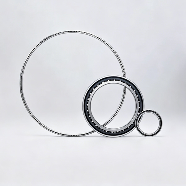
The industry discussion around crossed roller systems often focuses on stiffness and positioning accuracy. Those qualities matter, but the practical selection issue is duty-specific. A linear slide may repeatedly reverse over a limited travel range. A rotary table may index, oscillate through a small angle, or rotate for long periods in one direction. Each pattern can place the rolling contact and lubricant under different conditions.
This article provides an evergreen application-selection analysis rather than a market forecast. It applies to OEM engineers evaluating a crossed roller arrangement before finalizing a slide, turntable, indexing axis, or compact rotary module.
Comparison: Linear Reciprocating Duty Versus Rotary-Axis Duty
The first decision is to define the motion accurately. “Moving back and forth” and “rotating back and forth” may appear similar in a motion-control diagram, but their bearing contact paths, sealing exposure, and maintenance needs can differ substantially.
| Decision Factor | Linear Reciprocating Duty | Rotary-Axis Duty | Buyer Implication |
|---|---|---|---|
| Motion profile | Short or long linear travel with repeated reversal, acceleration, deceleration, and possible end-of-stroke dwell. | Continuous rotation, indexing, oscillation, or limited-angle positioning around a centerline. | Define whether the application needs a guided translation system or a bearing-supported rotary structure before requesting a bearing series. |
| Rolling contact path | Rolling elements travel along a linear raceway and may repeatedly pass through the same loaded zones in short-stroke use. | Rolling elements circulate around a circular raceway, while load zones can move relative to the ring during rotation. | Short repetitive motion deserves special attention because local raceway loading may dominate the service condition. |
| Lubrication behavior | Reversal can redistribute lubricant differently from continuous travel. Small stroke movement may not spread lubricant across the full usable raceway. | Rotation may distribute lubricant around the raceway, but speed, heat, orientation, and centrifugal effects can change film behavior. | Select lubricant and relubrication access based on actual duty, not only catalog load ratings. |
| Sealing exposure | Open slide arrangements may face chips, abrasive dust, coolant, cable debris, or handling contamination along the travel direction. | Rotary axes may face splash, airborne particles, process debris, or contaminants entering through adjacent housings and interfaces. | Specify the surrounding enclosure and contamination source. A bearing alone cannot compensate for poor machine sealing. |
| Life-limit factors | Repeated reversal, concentrated load zones, misalignment, contamination, and insufficient lubricant coverage can limit useful life. | Moment loading, axial clamping force, radial loading, preload, friction torque, thermal effects, and mounting distortion may control performance. | Use a duty-cycle review instead of assuming that one nominal load value answers the life question. |
| Typical system form | Precision slide, inspection carriage, compact transfer unit, or short-stroke mechanism. | Rotary table, robotic joint, direct-drive turntable, harmonic drive output, or indexing fixture. | Choose the bearing architecture after confirming whether translation or rotation is the primary motion. |
Conclusion: crossed roller linear motion is appropriate when the machine needs high rigidity and controlled translation over a defined travel path. A crossed roller rotary axis is more suitable when a ring-shaped bearing must resist combined loads while maintaining rotational accuracy. The limit is simple: a rotary bearing is not automatically a linear guide, and a linear crossed roller arrangement is not automatically the right support for a rotating table.
For example, a short-stroke measuring carriage may need a crossed roller slide configuration because its central concern is straight travel, reversal behavior, and carriage stiffness. A CNC indexing table needs a rotary arrangement because it must carry workholding loads and overturning moments around a central rotation axis. These systems may share rolling-contact principles, but their housing design and failure risks are different.
What the Duty Profile Reveals Before a Bearing Is Selected
A useful selection process begins with observable operating conditions, not assumptions about the machine category. Engineers should document the motion profile in enough detail for the bearing supplier to assess the real application.
For linear reciprocating systems, confirm the stroke pattern
Record the working stroke: Identify whether travel is short and repetitive or whether the carriage uses a broad portion of the raceway. Short repetitive strokes can focus rolling contact in limited areas.
Identify reversal frequency: Rapid direction changes can affect lubricant distribution and raise the importance of smooth preload and mounting accuracy.
Map the applied load: Include process force, carriage weight, cable drag, tool force, and any offset that creates a moment load.
Check the environment: Coolant, abrasive dust, and assembly debris can change the practical requirement for covers, wipers, or external sealing.
Review service access: If lubrication points cannot be reached after machine assembly, the maintenance plan must be agreed before release.
The recommendation is to use a linear crossed roller configuration where compactness, guide rigidity, and accurate straight motion are the main requirements. It does not apply automatically to long-travel material-handling systems, highly contaminated travel paths without protection, or applications where a different guide design better matches the travel length and environmental conditions.
For rotary systems, define the load path through the table or joint
Separate radial, axial, and moment loads: A workpiece may create all three at once, especially when the load center sits away from the axis.
State the rotation type: Continuous rotation, intermittent indexing, limited-angle oscillation, and slow positioning can have different friction and lubrication demands.
Include drive arrangement: Gear drive, torque motor, harmonic drive, or belt drive can introduce forces that affect the bearing and housing.
Confirm mounting stiffness: Ring bearings depend on accurately prepared mounting faces. Distortion from uneven tightening or an unsuitable housing can affect runout and torque behavior.
Define accuracy targets: Specify the needed runout, repeatability, tilt stiffness, and allowable friction torque at the system level.
When the main function is rotary positioning under combined loading, a dedicated rotary table bearing is generally the more direct option. BY Bearings offers BRT Rotary Table Bearings for applications where a table or axis must manage radial, axial, and overturning loads. This is not a substitute for application review when the machine has unusual thermal exposure, shock loading, highly variable workpiece mass, or uncertain mounting stiffness.
Linear Guide Versus Crossed Roller Bearing: Avoid the Wrong Comparison
The phrase “linear guide versus crossed roller bearing” can create confusion because the two terms may describe different parts of a motion system. A linear guide is usually evaluated as a translation solution. A crossed roller bearing may be used in a linear guide arrangement or as a rotary bearing, depending on its form and mounting method.
The better question is: what must the assembly constrain, and what motion must it allow?
| Application Need | Preferred Starting Point | Reasoning | Limit of the Recommendation |
|---|---|---|---|
| Short, highly controlled linear travel with high stiffness | Crossed roller linear arrangement | The rolling elements and raceways can provide precise guided movement in a compact envelope. | Check local contact conditions if the stroke repeatedly uses only a small part of the travel. |
| Rotary indexing under radial, axial, and moment loads | Crossed roller or rotary table bearing arrangement | A ring-based arrangement is suited to supporting a rotating structure around a central axis. | Housing rigidity, preload, lubrication, and bolt pattern must be evaluated with the full assembly. |
| Large-diameter rotating structure with lower positioning demands | Slew bearing arrangement | A slew bearing may suit applications where the machine needs large-diameter rotational support. | It should not be selected purely by diameter when high accuracy and low runout are required. |
| Compact robotic or harmonic-drive output joint | Crossed roller bearing matched to the joint structure | The bearing can carry combined joint loads while fitting a compact axis design. | Joint stiffness also depends on gearbox structure, housing, shaft fits, and assembly preload. |
For a robotic or compact automation axis, the question of when to use crossed roller bearings should be answered by combined load demand and space constraints, not by brand familiarity or a general preference for high precision parts. The bearing is one element in the accuracy chain. Motor control, transmission error, structure stiffness, mounting face quality, and thermal condition can all influence final positioning results.
BY Bearings supports OEM and ODM customization for special dimensions and mounting requirements. This can be useful when an existing housing cannot accept a standard ring geometry. However, customization should follow a confirmed drawing review. It does not remove the need to validate fits, fastening, lubrication route, and system-level tolerance stack.

Selection Procedure for OEM Slides and Rotary Positioning Axes
Use the following procedure before sending an RFQ. It helps prevent a technically correct bearing family from being installed in an unsuitable system arrangement.
Classify the primary motion. Mark the axis as linear translation, continuous rotation, indexing rotation, limited-angle oscillation, or a combined motion. Do not classify by machine name alone.
Draw the load path. Show where radial force, axial force, and overturning moment enter the bearing or guide. Include off-center payloads and drive forces.
Define the duty cycle. Record acceleration, deceleration, dwell, reversal, rotation pattern, and expected operating schedule. Where these details are not known, identify them as open assumptions rather than hiding them.
Describe the environment. State whether the assembly sees coolant, dust, process particles, washdown, vacuum-related requirements, or clean equipment conditions.
Set accuracy priorities. Rank runout, stiffness, friction torque, repeatability, noise, and load capacity. Not every project requires the same trade-off.
Review the mounting structure. Provide shaft and housing drawings, mounting face details, screw locations, and available lubrication access.
Request the matching bearing family. For rotary tables, review Rotary Table Bearings. For compact cross-roller rotary applications, identify whether a standard series or an OEM design is required.
Plan verification before volume release. Confirm inspection requirements, assembly instructions, incoming checks, and the tests used to accept the completed axis.
This process suits early application selection and supplier communication. It does not replace detailed life calculation or machine validation, particularly where load spectra, shock events, temperature, or contamination levels are uncertain.
Common Selection Mistakes That Change Bearing Results
Using nominal load as the only decision input. Load capacity matters, but it does not describe reversal frequency, mounting distortion, contamination, or friction requirements. Use a complete duty description instead.
Assuming a short-stroke slide behaves like a long-travel guide. Repeated motion over a limited zone can create a different contact pattern. Confirm the actual working travel, not the maximum physical travel.
Ignoring overturning moment on a rotary table. A load placed away from the centerline can affect tilt stiffness and bearing loading. Include fixture and workpiece offset in the RFQ.
Leaving lubrication responsibility undefined. Establish lubricant type, supply method, relubrication interval, and service access at the design stage. The correct plan depends on the operating environment and duty.
Specifying a precision class without a system target. Bearing precision should connect to the required machine runout and positioning result. A high-grade bearing cannot correct an unsuitable housing face or poor assembly practice.
Requesting a direct interchange without confirming interfaces. Dimensions may be only one part of compatibility. Mounting holes, preload condition, lubrication ports, sealing space, and load direction must also match.
At BY Bearings, quality control is managed under an ISO 9001 quality system, with 100% inspection before shipment. For applications requiring very tight rotary accuracy, grinding accuracy can reach P2 class and runout is controlled within 1.5 μm. These are manufacturing and inspection strengths, not a blanket guarantee of installed machine accuracy. Final results still depend on the customer’s housing, shaft, assembly method, and operating conditions.
How to Interpret Application Evidence and Remaining Uncertainty
Available application evidence can guide a discussion, but it should be kept in scope. BY Bearings has supplied P2 rotary table bearings for gear grinding applications in Mexico and crossed roller bearings for semiconductor equipment in Germany. These cases indicate that precision rotary and clean equipment applications can require close control of bearing performance. They do not prove that every gear-grinding machine or semiconductor tool needs the same bearing design.
A reasonable interpretation is that applications with high stiffness, controlled runout, low vibration, or compact combined-load support may benefit from a crossed roller arrangement. An alternative explanation for a machine problem may be poor housing flatness, insufficient support structure, thermal growth, motor tuning, contamination, or incorrect preload. Buyers should avoid attributing all vibration or positioning errors to the bearing before checking the full axis.
The signals that should change your selection are clear:
If the slide uses a very short repetitive travel, ask for a review of local raceway loading and lubrication strategy.
If the rotary table carries a heavy offset fixture, provide the overturning moment and mounting drawing for evaluation.
If the equipment works near chips, coolant, dust, or process particles, prioritize enclosure and sealing design before specifying accuracy class.
If low torque or quiet motion is the primary requirement, define the measurement method and acceptance condition for the completed assembly.
If installation accuracy is uncertain, review housing and shaft tolerances before choosing a higher precision grade.
For machine-tool builders, the related guidance on Bearings for Machine Tools can help frame rotary-axis requirements alongside the bearing selection. For direct-drive designs, bearing friction, heat behavior, and table structure should be considered together rather than as separate purchasing items.
Buyer Checklist Before Specifying a Crossed Roller Configuration
Use this checklist to decide whether the application is ready for bearing selection:
Is the primary motion clearly identified as linear, rotary, or combined?
Have radial, axial, and moment loads been separated and shown on a drawing?
Is the travel or rotation pattern known, including reversals and dwell periods?
Has the required system outcome been ranked: stiffness, runout, torque, noise, repeatability, or load support?
Are lubrication route, sealing space, and contamination sources documented?
Are housing, shaft, mounting face, and fastening details available for review?
Is the requested bearing precision matched to the final machine requirement rather than selected in isolation?
Has the project team identified what remains uncertain and what test will resolve it?
If you are selecting a linear slide or rotary positioning axis, submit your drawing and duty details to get a quote with BY Bearings.
 +8618939019135
 sales@bybearings.com
 +8618939019135

