
How BRT Rotary Table Bearings Fit Indexer Housings
Why Your Rotary Indexer Bearing Won't Fit (Even When Dimensions Match)
You've selected a BRT rotary table bearing with an inner diameter, outer diameter, and width that perfectly match your rotary indexer's specifications. Yet, during assembly, it doesn't seat correctly. The mounting holes are slightly off, or the bearing binds against a shoulder. This frustrating scenario is common and stems from overlooking three critical boundary dimensions beyond the basic ID/OD/Width: the housing bore geometry, the shoulder height, and the bolt hole pattern.
These high-rigidity bearings, also known as YRT bearings, are designed for extreme precision in applications like CNC rotary tables, turn-mill centers, and indexing heads. Their integrated structure, combining axial and radial rollers, demands an equally precise fit with the housing and shaft to deliver their specified performance. A seemingly minor mismatch in a supporting surface can lead to ring distortion, increased friction torque, and a dramatic loss of rotational accuracy.
At BY Bearings, with over 15 years of precision manufacturing experience, we frequently assist engineers in troubleshooting these exact fitment problems. This guide breaks down the critical interface dimensions you must verify to ensure a successful installation of BRT Rotary Table Bearings, preventing costly rework and downtime.
Beyond Bore & OD: The Three Fitment Deal-Breakers
A bearing's catalog dimensions are only the starting point. For integrated units like BRT bearings, the geometry of the mating components is just as important as the bearing itself. A perfect bearing cannot compensate for an imperfect housing. Before machining or assembly, you must validate these three areas.
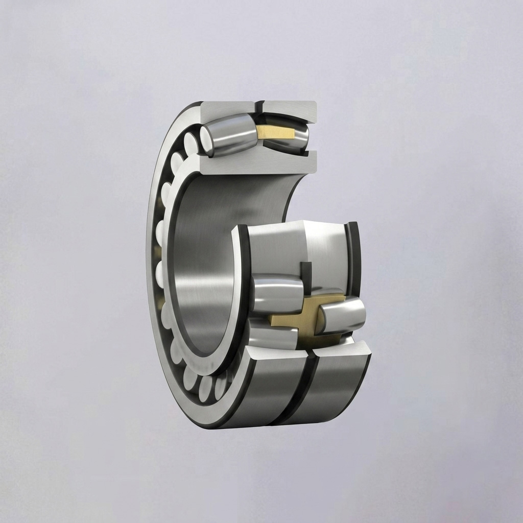
Here is a breakdown of the key parameters, their practical effects, and how to verify them against your BRT bearing installation drawing.
| Boundary Dimension | What It Affects | How to Verify |
|---|---|---|
| Housing Bore & Shaft Seat Diameters | This determines the fundamental fit (clearance, transition, or interference). An oversized bore prevents proper centering and support, leading to runout. An undersized bore can compress the outer ring, reducing internal clearance and causing premature failure. | Use a bore gauge to measure the housing diameter at multiple points and depths to check for roundness and taper. Compare these measurements against the recommended housing tolerances specified on the bearing drawing. |
| Shoulder Height & Perpendicularity | The housing and shaft shoulders provide axial support and ensure the bearing is square to the axis of rotation. If a shoulder is too high, it can interfere with the bearing's rotating ring or seals. If it's not perfectly perpendicular to the bore, it will tilt the bearing, inducing wobble and uneven load distribution. | Measure the shoulder height from the mounting face. Use a dial indicator and a precision square to check that the shoulder face is perpendicular to the bore centerline. Any deviation must be within the tolerance specified for the bearing's precision class. |
| Mounting Bolt Pattern (PCD & Hole Size) | Even if the bolt Pitch Circle Diameter (PCD) is correct, oversized or misplaced holes allow the bearing to shift during operation. Undersized holes will prevent fasteners from being installed. Incorrect PCD means the holes simply won't align, making mounting impossible without rework. | Verify the PCD using a CMM, a digital height gauge with a rotary table, or a printed 1:1 scale CAD drawing overlay. Check the diameter of each tapped hole in the housing and clearance hole in the bearing. Ensure they match the fastener specifications. |
Achieving Precision Fit: Tolerances, Surface Finish, and Runout
The performance of a P4 or P2 precision bearing is entirely dependent on the quality of its installation environment. Our manufacturing process, governed by a strict ISO 9001 Quality Control system, ensures every bearing meets its specifications, with total runout controlled within 1.5 μm. To translate that component-level accuracy to system-level performance, the mounting surfaces must be prepared with equal care.
Matching Tolerances to Precision Grade
The required tolerances for the housing bore and shaft seat diameter are directly linked to the bearing's precision class. A P2 grade bearing requires a much tighter tolerance on its mating parts than a P5 grade bearing. Always refer to the manufacturer's installation drawing for the specific H7, J6, or similar fit recommendations.
Housing Bore: Typically requires a transition fit (e.g., H6 or H7) to allow for precise positioning without distortion.
Shaft Seat: Usually requires a light interference or transition fit (e.g., j5 or k5) to prevent rotation on the shaft.
Surface Finish: The mounting surfaces for the bearing faces and diameters should have a low surface roughness (typically Ra 0.8 μm or better) to ensure uniform contact and load distribution.
Attempting to install a P2 bearing into a housing machined with P5 tolerances will negate the bearing's accuracy. The slight variations in the housing will distort the bearing's thin-walled rings, increasing rotational runout far beyond the 1.5 μm the bearing itself is capable of.
Common Mistakes in Rotary Indexer Bearing Fitment
Based on my experience helping customers with Bearings for Machine Tools, several recurring mistakes can compromise an otherwise perfect installation. Avoiding them is key to achieving optimal performance and longevity.
Uneven or Incorrect Bolt Torquing: BRT bearings have a series of mounting bolts on both the inner and outer rings. These must be tightened in a star pattern and in multiple stages to the specified torque value. Applying full torque to one bolt at a time will warp the bearing rings, creating high spots that increase friction and degrade accuracy.
Failure to Clean Components: Even a tiny metal chip, burr, or piece of grit on a mounting surface can prevent the bearing from seating flat. This introduces tilt, which directly translates to axial runout (wobble) at the workpiece. All components must be surgically clean before assembly.
Reusing Old or Incorrect Fasteners: Mounting bolts are a critical part of the assembly. Always use new, high-strength (e.g., Class 10.9 or 12.9) fasteners as specified. Using lower-grade bolts or reusing stretched bolts risks fastener failure or the inability to achieve and maintain the correct clamping force.
Ignoring Housing Rigidity: The housing itself must be rigid enough to support the bearing without deflecting under load. If the housing wall is too thin, the operational loads from cutting or acceleration can cause it to flex, which in turn distorts the bearing's outer ring and compromises the entire system's stiffness.
Real-World Application: P2 Precision for Gear Grinding
The importance of a perfect fit is clear in high-stakes applications. A customer in Mexico developing a new gear grinding machine required a rotary table with exceptional positioning accuracy and stiffness to meet DIN class gear quality standards. Any runout or deflection in the table would be directly transferred to the gear tooth profile, causing errors.
They selected one of our P2 grade BRT rotary table bearings. Our engineering team worked with them not just on the bearing selection but also on the housing and shaft design. We provided detailed drawings specifying the required H6 housing bore tolerance, shoulder perpendicularity of 2 μm, and a surface finish of Ra 0.4 μm for all mating surfaces.
By controlling these interface dimensions as tightly as the bearing itself was controlled, the customer's final assembly achieved the target micro-radian positioning accuracy. This case highlights that the bearing is just one part of a precision system. The successful integration, supported by our flexible OEM and ODM services, was the key to achieving their performance goals. This level of collaboration is standard for our clients, including those in Germany using our BBH Series Crossed Roller Bearings for semiconductor equipment.
If you are designing a new rotary axis or struggling with fitment issues on an existing one, validating these boundary dimensions is the first step. For complex applications or custom requirements, our team can help review your design to ensure a perfect fit.
Have questions about your specific application or need help with a custom design? Submit your drawings and we can provide a detailed technical review and get a quote.
 +8618939019135
 sales@bybearings.com
 +8618939019135

