
How Rotary Table Bearings Carry Combined Loads
How can one bearing arrangement support a workpiece weight, cutting force, side load, and overturning moment at the same time? This is the main question CNC machine designers and maintenance engineers must answer when selecting Rotary Table Bearings.
A rotary table is rarely loaded in one direction only. A vertical machining center table may carry axial force from the fixture and workpiece, radial force from off center cutting, and a tilting moment created when the cutting point sits away from the table centerline. If the bearing is selected only by static load rating, the table may still show runout, chatter, unstable positioning, or early wear.
The correct selection starts with the load path. Buyers need to understand where each force enters the bearing, which rolling elements carry it, how preload changes stiffness, and how mounting structure affects final accuracy. This article explains those points for CNC rotary tables, turn mill centers, direct drive tables, and indexing equipment.
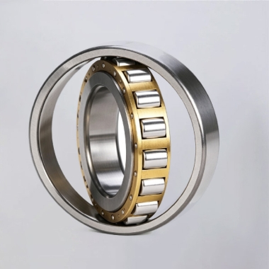
Identify the Combined Loads Before Choosing the Bearing Arrangement
Combined load capacity is not a single number that can be checked in isolation. It is the bearing system’s ability to carry several forces at once while maintaining acceptable rotation accuracy, torque, stiffness, and service life.
For a rotary axis, the three main external loads are axial force, radial force, and tilting moment. They often occur together during machining. A fixture plate may create continuous axial loading, while an offset workpiece creates a moment load even before cutting begins. During milling, interrupted tool contact can add changing radial forces and repeated moment reversal.
| Load Type | Typical Source | What It Affects in Practice | Risk When Underspecified |
|---|---|---|---|
| Axial load | Workpiece weight, clamping force, vertical cutting force | Table height stability and thrust support | Axial displacement, uneven contact, reduced positioning consistency |
| Radial load | Side cutting force, belt force, eccentric fixture mass | Centering accuracy and radial guidance | Radial runout, bore wear, unstable tool engagement |
| Tilting moment | Offset cutting point, cantilever fixture, uneven workpiece mass | Angular stiffness and table flatness under load | Table rocking, chatter marks, poor surface finish |
Selection conclusion: use a bearing arrangement designed for all three load directions when the table must machine parts under offset or changing forces. This approach fits turn mill centers, grinding tables, machining center rotary axes, and direct drive tables. It does not mean every small indexing device needs a high precision rotary table bearing; a low load indexing application may use a simpler arrangement when accuracy and moment demand are modest.
Machine designers should also separate applied load from required performance. A bearing may survive a given force but still permit more deflection than the process can accept. For finish grinding, even small angular movement can affect part geometry. For rough positioning equipment, greater deflection may be acceptable if indexing repeatability remains within the machine requirement.
Load Path Breakdown for Axial Radial and Tilting Moment Forces
The load path explains how force moves from the machine table into rolling elements and then into the machine base. This is the practical reason YRT style and crossed roller arrangements can support combined loading in a compact envelope.
In a typical rotary table bearing, axial loads are carried through thrust rolling elements or angled rolling contacts. Radial loads are carried through a radial guiding section or through rolling elements arranged to accept radial force. Tilting moments create higher load on one side of the bearing and reduced load on the opposite side. The bearing must have enough stiffness, contact support, and preload control to resist this uneven distribution.
| Force Direction | Load Path Through the Assembly | Primary Bearing Response | What Buyers Must Check |
|---|---|---|---|
| Axial force downward | Table surface to rotating ring, then through loaded thrust rolling elements into the stationary ring and base | Supports vertical load and limits axial displacement | Axial rating, mounting face flatness, preload condition, fixture weight |
| Axial force upward | Table surface to rotating ring, then through the opposite thrust contact path into the base | Resists lifting force during clamping or upward cutting action | Bidirectional thrust capability and secure ring clamping |
| Radial force | Table centerline shifts force into radial rolling contacts and then into the housing bore | Keeps the rotating axis centered relative to the base | Housing geometry, shaft fit, radial load direction, drive side force |
| Tilting moment | Offset force increases contact load on one bearing side while unloading the opposite side | Creates a resisting couple across the bearing diameter | Moment rating, support diameter, preload, ring stiffness, table overhang |
What happens under moment load: imagine a heavy fixture positioned near the outer edge of a rotary table. The fixture creates a lever arm from the centerline. The bearing does not receive only the fixture weight; it receives a force multiplied by the offset distance. The loaded side of the bearing sees greater rolling element contact force, while the opposite side may lose contact if preload is insufficient.
Practical conclusion: when the fixture or cutting point is offset, moment stiffness usually becomes more important than axial load alone. This applies to large face milling, off center drilling, turbine component machining, and fixtures with tall clamping structures. It is less dominant when the workpiece is centered, compact, and machined with light forces.
For this reason, a buyer should not compare only the nominal table diameter. Two units with similar dimensions can behave differently if their rolling element arrangement, contact geometry, preload, or mounting ring stiffness differs.
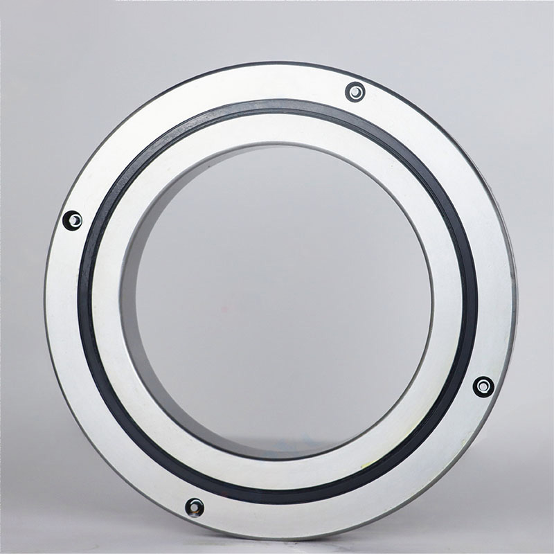
Choose the Bearing Design That Matches the Machine Load Pattern
YRT type designs are commonly selected where high axial stiffness, radial guidance, and tilting resistance are required in one integrated unit. They are suitable for machine tool bearings used in rotary tables, indexing systems, and precision turntables. BY Bearings supplies BRT Rotary Table Bearings for applications requiring combined load support and controlled rotational accuracy.
Crossed roller bearings use cylindrical rollers arranged alternately at right angles. This arrangement allows one compact bearing to accept radial, axial, and moment forces. They are often a good fit where installation height and compact integration matter, such as robotics, automation joints, and some direct drive assemblies.
| Bearing Option | Best Fit | Combined Load Behavior | Limits to Consider |
|---|---|---|---|
| YRT style arrangement | CNC tables, indexing tables, grinding equipment | Designed to manage axial, radial, and moment loads with high stiffness | Requires accurate mounting faces and controlled installation torque |
| Crossed roller arrangement | Compact rotary axes, robotics, automation equipment | Supports multi direction loading in a compact section | May need careful preload selection for torque sensitive drives |
| Crossed tapered arrangement | Heavy moment applications and demanding rotary systems | Suitable where high rigidity under combined forces is needed | Space, mounting design, and operating speed must be reviewed |
| Slew bearing arrangement | Large diameter, slower rotating structures | Handles axial, radial, and moment loads in larger structures | Usually not the first choice for high precision CNC positioning |
Selection conclusion: select a YRT type unit when the application needs a defined precision bearing package for a machine tool rotary axis. Select Precision Crossed Roller Bearings when compact structure and multi direction capability are the main design priorities. Consider Crossed Tapered Roller Bearings when high tilting moment stiffness is required. Large construction equipment and slow rotation platforms may instead require Slew Bearings.
The limit is application context. A bearing type that works well in a robotic joint may not provide the required table stiffness for heavy cutting. Conversely, a large machine tool arrangement may add unnecessary size, friction torque, and cost to a lightweight automation axis.
Use Preload and Mounting Accuracy to Preserve Table Stiffness
Bearing preload control is the intentional internal loading that removes unwanted clearance and helps maintain rolling contact during changing load directions. In a rotary axis, preload affects stiffness, friction torque, temperature behavior, and resistance to vibration.
Too little preload can allow the rolling elements on the unloaded side to lose effective contact under a reversing moment. The result may be table rocking, backlash like movement, or vibration during interrupted cutting. Too much preload can increase friction torque, heat generation, and wear. This can be especially troublesome in direct drive systems where motor torque must overcome bearing resistance at low speed.
Recommendation: use the preload condition specified for the bearing and intended operating duty. This fits precision machining and positioning equipment where stiffness and repeatability matter. Do not increase preload simply to compensate for poor mounting surfaces, a weak housing, or excessive table overhang. Those structural issues must be corrected at the machine design level.
Mounting geometry matters just as much. A high quality bearing cannot correct a table face that is distorted, contaminated, or unevenly clamped. Before installation, inspect the locating shoulder, housing bore, table face, mounting bolt pattern, and ring seating condition. Tighten mounting fasteners progressively in a controlled pattern so the ring is not pulled unevenly against the mounting surface.
For demanding CNC work, inspect assembled runout and turning torque after installation. BY Bearings controls grinding accuracy up to P2 class and states runout control within 1.5 μm for applicable precision products, with 100% inspection before shipment under its ISO 9001 quality system. Final machine performance still depends on the spindle, housing, table structure, assembly process, and operating load.
Follow a Practical Selection Procedure Before Requesting a Quote
A useful RFQ gives the supplier enough information to check whether the bearing can carry the real load path. The process below helps prevent a selection based only on outside diameter or an existing part number.
Define the axis orientation. State whether the table is horizontal, vertical, tilted, or changes orientation during operation. Gravity affects the continuous axial or radial load direction.
List workpiece and fixture mass. Include their center of gravity and maximum offset from the rotation center. This identifies the static moment component.
Describe machining forces. Provide expected axial, radial, and tangential cutting forces, including peak conditions and load reversals.
Identify the support geometry. Share table diameter, mounting dimensions, housing dimensions, shaft arrangement, and available installation height.
Set performance targets. Specify rotary table accuracy, acceptable runout, stiffness expectations, speed range, duty cycle, and allowable friction torque.
Confirm environmental conditions. Include coolant exposure, chips, lubrication method, temperature variation, and cleanliness needs.
Submit drawings. A section drawing and mounting details allow the supplier to review the actual load path instead of making assumptions.
This procedure fits both new machine design and replacement projects. For replacement, do not assume dimensional interchangeability alone confirms performance. An existing bearing may have been selected for a lighter workpiece, lower duty cycle, or different machining process.
BY Bearings supports OEM and ODM requirements, including flexible customization, and operates a 13,500 m² intelligent factory with CNC workshop and automated heat treatment line. For special mounting holes, ring dimensions, or replacement design review, drawings are more useful than a short bearing code alone.
Avoid Common Errors That Reduce Combined Load Performance
Selecting by axial load only. This can work for centered, lightly loaded tables, but it does not address the moment created by an offset fixture or side cutting force.
Ignoring table overhang. A larger overhang increases the tilting effect. Reduce overhang where possible or select a bearing and structure intended for the resulting moment.
Using preload to fix structural weakness. More preload may mask looseness briefly, but it can raise torque and heat. Improve the housing, mounting face, and table stiffness first.
Overlooking load reversal. Milling, indexing, acceleration, and deceleration can reverse force direction. Check both directions rather than using a single static load case.
Skipping installation checks. Dirt under the ring, uneven bolt tightening, or a damaged locating shoulder can create local distortion and runout.
Requesting only a price. A low price comparison without duty cycle, speed, load position, and accuracy requirements may lead to an unsuitable option.
A real application example is precision gear grinding. BY Bearings has supplied P2 rotary table bearings for gear grinding in Mexico. This type of application requires attention to runout, stiffness, and mounting accuracy because the process can expose small errors in the rotary axis. The case should not be treated as a universal specification for every machine; each table requires its own load and accuracy review.
Verify Quality Controls and Supply Requirements for CNC Projects
For CNC machine builders, bearing selection does not end with catalog comparison. The supplier should be able to provide dimensional data, accuracy grade information, inspection approach, material details where needed, and support for mounting questions.
BY Bearings uses premium GCr15 bearing steel verified by spectrographic analysis and performs metallographic examination after heat treatment to check hardness and martensitic structure. Its quality controls include 100% pre shipment inspection. Buyers can review the stated inspection approach through Precision Bearings Quality Control before finalizing a sourcing decision.
For supply planning, BY Bearings has a monthly production capacity of 15,000 sets, supports no minimum order quantity, and offers a 12 month warranty from shipment date. The company also holds CE and RoHS certifications and exports to more than 65 countries, serving more than 500 B2B customers. These points are relevant when a project needs prototype quantities, replacement parts, or recurring OEM supply.
Ask for selection advice or get a quote with your table drawing, load data, speed range, and accuracy target.
 +8618939019135
 sales@bybearings.com
 +8618939019135

