Precision Crossed Roller Bearings Accuracy FAQs
How Precision Crossed Roller Bearings Affect Rotary Accuracy
Why does a rotary axis still show positioning error after a high accuracy bearing has been installed? This is one of the most common questions from design and maintenance teams working with robotics, machine tools, semiconductor equipment, direct drive tables, and inspection systems.
Precision Crossed Roller Bearings can provide high radial, axial, and moment stiffness in a compact arrangement, but the bearing is only one part of the final accuracy chain. Housing bore accuracy, shaft geometry, mounting surface flatness, tightening sequence, preload, lubrication, and measurement method can all affect the result seen at the load point.
The practical goal is not simply to buy the highest available accuracy grade. The goal is to identify which component limits the assembly, specify the bearing accordingly, and make sure the mounting parts can preserve that accuracy after installation.
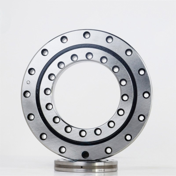
What accuracy can a crossed roller bearing contribute?
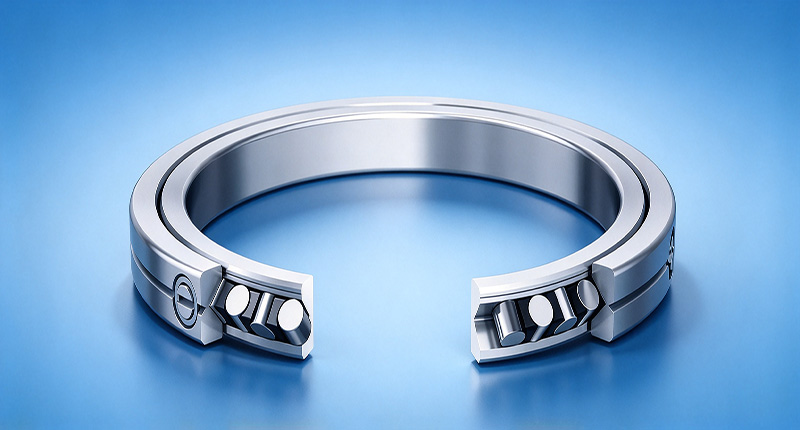
A crossed roller bearing uses cylindrical rollers arranged alternately at right angles. This structure allows one bearing to carry radial loads, axial loads in both directions, and overturning moments. It is well suited to compact precision rotary assemblies where two conventional bearings would add length, compliance, or alignment risk.
The bearing contributes to accuracy through ring geometry, roller matching, internal clearance or preload, and rotational consistency. It does not automatically correct errors in surrounding components. A highly accurate bearing installed on an out of round housing bore will still follow the distortion imposed by that housing.
| Accuracy factor | What the bearing can influence | What the bearing cannot correct | Best fit |
|---|---|---|---|
| Radial runout | Rotational variation caused by bearing ring and rolling element geometry | Shaft eccentricity, housing distortion, or an uneven mounting shoulder | Rotary indexing units and inspection tables |
| Axial runout | Face movement during rotation | Warped mounting surfaces or uneven bolt tightening | Grinding tables and vertical rotary axes |
| Tilting stiffness | Resistance to moment loads through crossed roller contact geometry | Flexible supporting structures or insufficient mounting rigidity | Robot joints and cantilevered loads |
| Rotational torque | Consistency affected by bearing geometry, preload, lubrication, and cleanliness | Motor cogging, seal drag, gear backlash, or misaligned mounting parts | Direct drive turntables and low speed scanning equipment |
Conclusion: select the bearing based on the accuracy requirement at the functional load point, not only the bearing catalogue value. This approach fits equipment with demanding repeatability requirements. It does not remove the need to control the housing, shaft, mounting faces, and drive system.
For compact radial and axial load support, review our Precision Crossed Roller Bearings. Where the machine requires an integrated arrangement for a rotary axis, Rotary Table Bearings may be a more suitable product category.
When does the housing bore, shaft fit, or mounting surface limit accuracy?
The direct answer is simple: the installed system is limited by the weakest geometric interface. If the housing bore, shaft seat, mounting shoulder, or mounting surface has a larger error than the bearing can tolerate, the final axis accuracy will be controlled by that installation error rather than by the bearing itself.
This boundary matters before procurement. A P2 class bearing can be justified for a demanding rotary application, but it cannot deliver its intended performance if the installation parts introduce distortion or runout.
| Question | Direct answer | Why it happens | What to check |
|---|---|---|---|
| Can a high accuracy bearing correct a poor housing bore? | No. | An incorrect bore can deform the outer ring or create uneven contact around the circumference. | Measure bore size, roundness, taper, and the shoulder condition before assembly. |
| Can shaft fit affect rotational runout? | Yes. | A shaft seat with eccentricity, taper, burrs, or poor surface condition transfers error to the inner ring. | Check shaft fit, shoulder squareness, and runout near the bearing seat. |
| Can mounting surface flatness cause axial error? | Yes. | An uneven surface can tilt the ring when bolts are tightened. | Inspect mounting surface flatness, cleanliness, and contact marks. |
| Can bolt tightening change torque? | Yes. | Uneven tightening can distort thin bearing rings and alter internal load distribution. | Use a staged cross pattern and monitor rotation during tightening. |
| Can preload solve structural looseness? | No. | Preload addresses internal bearing clearance, not flexible housings, loose fasteners, or drive backlash. | Assess the complete load path and mounting rigidity. |
Housing bore accuracy: the housing must support the outer ring evenly. If the bore has localized high spots, taper, or damage, installation force may distort the ring. This can increase rotational torque variation and reduce usable runout performance. This guidance is especially relevant for thin rings and compact housings. It is less significant when the bearing design includes a stiff integral housing, but the mounting interface still requires inspection.
Shaft fit: a shaft seat should provide controlled support without forcing the inner ring into an unwanted shape. Excessive interference can create mounting stress. An overly loose fit can allow creep or movement under reversing loads. The right approach depends on ring rotation, load direction, temperature difference, and whether the application experiences vibration. Do not apply one standard fit to every assembly.
Mounting surface flatness: the bearing ring needs even face support. Dirt, paint, raised burrs, thread damage, or a warped flange can produce tilt when screws are tightened. This is common during maintenance work because a replacement bearing may be blamed for an error that was already present in the mounting structure.
Bearing runout control: measure the installed assembly instead of relying only on an individual bearing inspection value. Measure the shaft, housing, mounted ring, and final working face separately. That sequence helps the team identify whether the source is the bearing, the mounting parts, or the drive train.
Which bearing accuracy level fits the application?
The right grade depends on the machine function, the allowable error at the tool or load point, the stiffness of the surrounding structure, and the measurement method used for acceptance. Higher bearing accuracy is useful when the rest of the assembly is designed and manufactured to support it.
BY Bearings manufactures P5, P4, and P2 high accuracy bearings. Grinding accuracy can reach P2 class, with runout controlled within 1.5 μm for applicable precision products. This level of control is most valuable when the customer also provides suitable mounting conditions and a clear inspection requirement.
| Application situation | Recommended selection focus | Reasoning | Limit |
|---|---|---|---|
| Industrial robot wrist joint | High rigidity and controlled preload | Joint backlash and moment loading can affect end effector positioning. | Bearing selection alone cannot correct gearbox backlash or arm deflection. |
| CNC rotary table | Low runout and high tilting stiffness | Cutting forces create radial, axial, and overturning loads. | Spindle condition, fixture balance, and table structure also influence machined surface quality. |
| Semiconductor handling axis | Low vibration and stable torque | Sensitive positioning systems require controlled rotational behavior. | Motor quality, encoder resolution, cable drag, and clean assembly conditions remain important. |
| Direct drive turntable | Consistent friction torque and suitable lubrication | Low speed motion can reveal torque fluctuation and drive disturbance. | Motor cogging and controller tuning may remain the main source of speed variation. |
| General automation fixture | Match accuracy to actual process tolerance | A balanced specification avoids paying for unused accuracy capability. | Do not reduce bearing grade if moment stiffness is still required. |
For machine tool indexing and turn mill applications, a purpose designed BRT Rotary Table Bearings arrangement may provide a better functional fit than a standard bearing layout. For compact robotic joints and harmonic reducers, bearing selection should include mounting geometry, load direction, internal clearance requirement, and the reducer interface.
A real application example is BY Bearings supplying P2 rotary table bearings for gear grinding equipment in Mexico. The application required a high accuracy rotary support arrangement. The useful lesson is that the bearing grade must be matched to the complete gear grinding axis, including the table structure and mounting accuracy. It should not be treated as a stand alone cure for every machining error.
How should teams specify a bearing before requesting a quotation?
A quotation request becomes more accurate when it includes operating details rather than only an existing part number. If the design team is replacing an established bearing, the original drawing and measured installation conditions are often more useful than a short product description.
Define the load direction. State radial load, axial load, overturning moment, shock load, and whether the load reverses. This determines whether a standard crossed roller bearing is suitable.
Identify the rotation pattern. Confirm continuous rotation, indexing, oscillation, low speed movement, or frequent start stop operation. Torque behavior and lubrication needs differ between these conditions.
Set the functional accuracy target. State whether the priority is radial runout, axial runout, tilt, repeat positioning, torque consistency, or vibration reduction.
Provide mounting drawings. Include housing bore details, shaft fit details, mounting hole locations, shoulder geometry, and available assembly space.
State preload requirements. If bearing preload settings are specified, clarify whether the target is stiffness, elimination of looseness, torque control, or a combination of these factors.
Describe the environment. Include contamination risk, temperature conditions, lubrication preference, corrosion exposure, and clean equipment requirements.
Agree on inspection criteria. Define where and how runout or torque will be measured. A bearing measured on a test fixture may show different results after it is mounted in a machine.
Conclusion: submit drawings and acceptance criteria with the enquiry. This is the best approach for OEM projects, replacement parts with recurring accuracy issues, and customized mounting arrangements. It may be more information than needed for a standard catalogue replacement, but it prevents misunderstandings on critical assemblies.
What installation mistakes cause avoidable accuracy problems?
Many field problems are not material failures. They are installation or measurement issues that can often be prevented with a disciplined assembly process.
Installing over burrs or contamination: even a small raised area can tilt a ring. Clean the bore, shaft, shoulder, flange, and fastener contact surfaces before assembly.
Using impact force on the ring: impact can damage rolling elements or raceways. Use controlled assembly tools and apply force only to the ring being fitted.
Tightening bolts in a circular sequence: this can pull one section down first and distort the ring. Use a staged cross pattern with gradual tightening.
Ignoring torque changes during assembly: rising or uneven turning resistance can indicate mounting stress, contamination, or a seating problem. Investigate before the machine enters service.
Measuring only at one location: one indicator position may not identify the source of error. Measure the shaft, housing, ring face, and functional load surface where possible.
Assuming preload fixes wobble: preload cannot compensate for a flexible support structure, damaged flange, loose fasteners, or clearance elsewhere in the drive system.
Changing lubrication without review: grease type, quantity, and distribution can alter friction torque. Use the agreed lubrication approach for the application.
For installation teams, the most useful check is to record baseline rotation torque and runout after each assembly stage. Start with the prepared housing and shaft. Then measure after the bearing is seated, after fasteners are tightened, and after the working table or load flange is installed. This makes troubleshooting faster because the point where the error appears becomes visible.
How BY Bearings supports accuracy focused sourcing
Accuracy focused procurement needs more than a catalogue dimension match. BY Bearings has more than 15 years of precision bearing manufacturing experience and operates a 13,500 m² intelligent factory with CNC workshop and automated heat treatment line. Our monthly production capacity is 15,000 sets, supporting both regular supply and project based requirements.
Quality control is part of the sourcing decision. Our ISO 9001 quality system includes 100% inspection before shipment. BY Bearings also provides CE, RoHS, and TUV certified products where applicable. For demanding projects, our team can review drawings, mounting holes, special dimensions, and functional interchangeability requirements through OEM and ODM support.
We have supplied crossed roller bearings for semiconductor equipment in Germany and BBH crossed roller bearings for bulk export to Germany. These are specific customer cases, not a promise that every application has identical operating conditions. They do show that application details, inspection requirements, and stable supply need to be considered together.
For projects requiring compact radial capacity, compare BBH Series Crossed Roller Bearings with the available mounting envelope. If the project needs a different load arrangement, Crossed Tapered Roller Bearings may be worth evaluating with the engineering team.
Submit your drawings and accuracy targets to get a quote for bearing selection advice.
 +8618939019135
 sales@bybearings.com
 +8618939019135