
RE Series Crossed Roller Bearings Differences
Design engineers often ask one practical question during early component selection: should the application use a standard RE bearing, an RE-H high-rigidity version, or an REV full-roller version? The answer depends less on the bearing name and more on how the machine handles load, friction torque, mounting stiffness, and positioning repeatability.
RE Series Crossed Roller Bearings are designed for compact rotary and oscillating axes that must carry radial load, axial load, and overturning moment in one bearing position. Their crossed roller arrangement allows one ring set to support loads from multiple directions, making the series suitable for robotics, automation equipment, inspection devices, medical systems, and machine-tool axes.
BY Bearings supplies crossed roller bearings, harmonic drive bearings, crossed tapered roller bearings, rotary table bearings, slew bearings, thin section bearings, spherical roller bearings, cylindrical roller bearings, and thrust bearings for precision-motion applications. For engineers comparing compact crossed designs, our Precision Crossed Roller Bearings range provides a useful starting point. Applications with heavier table loads or integrated axial-radial support may instead require Rotary Table Bearings.
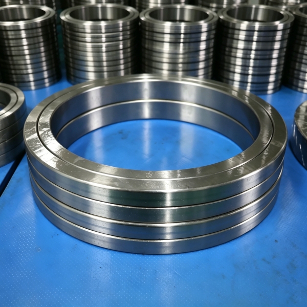
The key distinction is internal rolling-element arrangement. Standard RE and RE-H designs commonly use rollers separated by spacers or retainers, while REV designs use a fuller roller population. This changes friction behavior, load capacity, torque consistency, and the preferred operating duty.
Identify the construction difference before selecting an accuracy class
The RE, RE-H, and REV names are not simply alternative labels for the same bearing. They indicate different construction priorities. A buyer who selects only by outside diameter, bore diameter, and basic load rating can overlook the operating behavior that matters most in a precision axis.
RE bearings suit balanced precision positioning duties
A standard RE design is generally the balanced option when the machine requires combined-load support with controlled rotational behavior. Spacers or retainers keep adjacent rollers separated. That separation reduces roller-to-roller contact, helping the bearing produce more predictable friction torque during low-speed indexing, oscillation, and repeated positioning.
Choose this design when the axis is expected to stop frequently at defined positions, such as a compact robot wrist, optical inspection platform, or semiconductor handling station. The benefit is not simply “lower friction.” More stable torque makes it easier for the motor, controller, and encoder system to maintain consistent motion response.
It is not automatically the best choice for every high-load condition. Where the available bearing envelope is fixed and maximum load capacity is the primary target, a full-roller option may be more appropriate.
RE H bearings focus on higher structural rigidity
RE-H versions are intended for applications that demand greater rigidity under load. This makes them relevant when a structure experiences stronger overturning moments, changing cutting forces, or a long offset between the bearing centerline and the working point.
For example, a compact rotary fixture may carry a workpiece close to the bearing centerline during one cycle and farther away during another. That offset creates a larger moment load. A higher-rigidity bearing arrangement can reduce elastic movement at the output face, which helps preserve tool position or sensor alignment.
Select an RE-H type when machine stiffness is a primary concern and the housing and shaft are also sufficiently stiff. Do not expect a bearing alone to correct a thin housing, poor shoulder geometry, or loose mounting bolts. In those cases, the surrounding structure remains the limiting factor.
REV bearings prioritize roller quantity and load support
REV designs use a full-roller arrangement rather than a spacer-retainer arrangement. More rollers can occupy the raceway, increasing the available rolling-element contact positions. In practical terms, this often makes the full-roller construction a strong candidate where load capacity is more important than the lowest possible friction torque.
The tradeoff is operational. With rollers positioned directly next to each other, internal interaction can affect friction torque behavior more than in a spacer-retainer design. This does not make REV unsuitable for precision work. It means the engineer should assess torque variation, lubrication condition, preload, and the motor reserve needed for the actual motion profile.
REV is often a logical choice for heavily loaded, slow-turning, or intermittent indexing mechanisms. It may not be the preferred option for an axis where exceptionally smooth low-speed torque is the first design priority.
Comparison: spacer retainer and full roller designs
The internal roller arrangement affects what the machine experiences at the output shaft. The table below compares the two construction approaches used when evaluating RE, RE-H, and REV options.
| Selection factor | Spacer retainer design | Full roller design | What it affects in practice |
|---|---|---|---|
| Roller separation | Rollers are separated by spacers or retainers. | More rollers occupy the raceway without spacer separation. | Separation helps reduce roller interaction; fuller roller packing favors load support. |
| Friction behavior | Usually better suited to controlled, repeatable friction behavior. | May show greater sensitivity to roller interaction, lubrication, and preload. | Wrong selection can cause uneven low-speed motion or insufficient motor margin. |
| Torque stability | Better fit for precision indexing and frequent reversal. | Better suited where higher load support matters more than the lowest torque variation. | Torque stability affects settling time, servo tuning, and repeat-position consistency. |
| Load capacity | Balanced capacity for combined radial, axial, and moment loads. | Higher roller population can improve load-carrying potential within a similar envelope. | Choosing too light a design can increase deflection and shorten service life. |
| Application fit | Robotics, inspection axes, optical equipment, light to moderate precision tables. | Heavy fixtures, slow indexing mechanisms, and high-moment compact axes. | The best option follows the duty cycle, not only the bearing dimensions. |
Selection conclusion: use a spacer-retainer design when controlled torque behavior and smooth positioning are the leading requirements. Use a full-roller design when the installation must carry more load within a limited space and the drive system can accommodate the corresponding torque behavior. Neither approach is universally better.

Match RE, RE H and REV to the machine duty cycle
Duty cycle is the most useful filter after bearing envelope and mounting dimensions. Engineers should document not only the maximum load, but also how that load is applied over time.
- Frequent short indexing: Favor standard RE or RE-H construction when repeatable friction torque and stable response are required. This fits rotary inspection stations, pick-and-place modules, and compact robotic joints. It does not replace proper servo tuning or rigid mounting surfaces.
- Oscillating motion: A spacer-retainer arrangement is often the safer starting point when the axis repeatedly reverses through a short angle. The reason is that torque consistency becomes more visible during reversal. Confirm lubrication and preload requirements before finalizing the design.
- High overturning moment: Consider RE-H when the mounted arm, fixture, or spindle nose places load away from the bearing centerline. The higher-rigidity focus helps limit displacement, but only if shaft and housing shoulders are properly designed.
- Slow heavy rotation: Consider REV when the system needs stronger load support in a compact package and does not depend on the smoothest possible low-speed torque. Review drive torque reserve and operating temperature during validation.
- High accuracy machine axes: Assess the entire axis stack, including bearing accuracy, housing runout, shaft fit, mounting flatness, preload, lubrication, and encoder position. Bearing accuracy alone cannot deliver final table accuracy.
For turn-mill centers and multi-axis cutting systems, combined radial, axial, and moment loads may point to a different bearing family altogether. BY Bearings also provides BRT Rotary Table Bearings for precision rotary tables where axial-radial support and tilting stiffness are central selection factors.
Use a practical selection procedure before issuing drawings
A disciplined comparison prevents late design changes. The following procedure can be used during concept design, before the bearing is released on a production drawing.
- Define the motion profile. Record whether the axis rotates continuously, indexes, oscillates, or reverses. Include speed range, dwell periods, acceleration, and required positioning behavior.
- Calculate all applied loads. Identify radial load, axial load, and overturning moment at the bearing center. Do not evaluate only the vertical payload; fixture weight and offset often create the controlling moment.
- Set the priority. Rank torque stability, rigidity, load capacity, compactness, and service life. A design team should agree on the leading requirement before comparing bearing versions.
- Select the internal arrangement. Start with spacer-retainer construction for controlled torque behavior. Move toward full-roller construction when the load requirement cannot be met within the available space.
- Check the mounting design. Confirm shoulder support, mounting bolt layout, surface flatness, and ring location. Uneven support can distort the rings and create unwanted torque variation.
- Specify accuracy and inspection needs. Identify whether the axis needs standard precision or tighter runout control. BY Bearings can support P5, P4, and P2 precision requirements according to the application.
- Validate with the actual load path. Test the complete assembly with the production fixture, motor, gearbox, and encoder. A no-load spin test alone will not reveal all moment-load effects.
This process also helps determine when a crossed roller bearing is not the best family. If the application needs a large diameter, relatively low-speed rotating structure, Slew Bearings may be a more suitable route. If the design has strict radial space limits but does not require the same moment stiffness, Thin Section Bearings can be evaluated.
Prevent mounting and specification mistakes that change bearing behavior
Many bearing selection problems are actually mounting or specification problems. The following mistakes can change the behavior of a correctly selected RE, RE-H, or REV bearing.
- Selecting by catalog envelope only. Two bearings may fit the same space but behave differently under low-speed torque or high moment loading. Compare construction and duty cycle, not dimensions alone.
- Ignoring the moment arm. A small payload can create a large overturning moment when mounted far from the bearing centerline. Include fixture length, tooling, cables, and moving attachments in the load calculation.
- Using weak support structures. A rigid bearing mounted in a flexible housing cannot provide the expected output stiffness. Strengthen the surrounding assembly before upgrading bearing precision.
- Overlooking preload effects. Preload influences rigidity and friction torque. Too little preload can allow unwanted movement; excessive preload can increase torque and heat. Follow the bearing supplier’s installation guidance for the selected design.
- Assuming full roller means best precision. Full-roller construction can improve load support, but it is not automatically the best answer for torque-sensitive positioning axes.
- Skipping incoming verification. Confirm part marking, dimensions, rotation feel, mounting interfaces, and inspection documentation before assembly. This is especially important when replacing a bearing in an existing machine.
Apply the comparison to a compact rotary table example
Consider a compact rotary table carrying a fixture that indexes between machining or inspection positions. The fixture creates radial load, axial load, and a changing overturning moment as parts are added or removed. The table must stop accurately, and its motor has limited torque reserve during acceleration.
In this situation, a standard RE design is often the initial candidate because controlled torque behavior supports repeated indexing. If analysis shows that the fixture offset causes excessive elastic movement at the table face, the engineer should compare an RE-H option. The reason is not simply higher bearing strength; it is the need for improved resistance to displacement under moment loading.
If the fixture becomes substantially heavier while the table remains slow-moving and low-speed torque smoothness becomes less demanding, REV may become the more suitable candidate. Its fuller roller arrangement can better match the load-focused requirement. However, the designer must reassess drive torque, lubrication, and preload because those factors affect actual operating torque.
This comparison shows why bearing selection should not start with “which version is strongest?” The better question is: “Which internal design supports our actual motion and load priorities without creating a new control or mounting problem?”
Specify a supplier that can verify the selected bearing
For precision-motion projects, the supply partner should be able to support drawing review, inspection expectations, and customization requirements. BY Bearings has more than 15 years of precision bearing manufacturing experience and operates a 13,500 m² intelligent factory with CNC workshop and automated heat treatment line. Our ISO 9001 quality system supports 100% inspection before shipment.
For applications requiring tighter rotation accuracy, BY Bearings can provide grinding accuracy up to P2 class with runout controlled within 1.5 μm. These capabilities are relevant when the bearing directly influences table rotation, sensor alignment, gear grinding, or compact automation positioning. A documented Mexico application involved P2 rotary table bearings for gear grinding, demonstrating the type of precision requirement that should be defined early in the design stage.
OEM and ODM support is available for special dimensions and mounting requirements. When a standard RE, RE-H, or REV layout does not match the shaft shoulder, housing interface, or mounting-hole arrangement, share the assembly drawing and load information before committing to tooling or prototype quantities.
Submit your drawing and operating conditions to get a quote and receive selection advice for your RE, RE-H, or REV bearing application.
 sales@bybearings.com
 +8618939019135

