
Slew Bearings Ball vs Roller Ring Load Limit Guide
As a design engineer, selecting the correct slew bearing is a critical decision that directly influences the performance, safety, and longevity of heavy rotating equipment. The choice often comes down to two fundamental designs: ball or roller. While both can manage combined loads, their internal geometry creates significant differences in load capacity, stiffness, and suitability for specific applications. Understanding these differences is essential for avoiding premature failure, excessive deflection, and costly downtime.
Many specifications focus on static load ratings, but the real performance of Slew Bearings is determined by how they handle dynamic, multi-axis forces. A ball bearing might be sufficient for a slow-moving, lightly loaded turntable, but it would fail quickly under the heavy tilting moments experienced by a large excavator. This guide breaks down the core mechanical principles that distinguish these two designs, providing the technical clarity needed to make the right selection for your machinery.
Key Differences: Ball vs. Roller Contact Geometry
The fundamental distinction between ball and roller slew bearings lies in their contact geometry. This single factor dictates how loads are distributed across the raceways and ultimately determines the bearing's overall capacity and rigidity. A ball makes point contact with the raceway, while a roller makes line contact. This seemingly small difference has massive implications for performance under load.
Our 15+ years of manufacturing experience have shown that misinterpreting these differences is a common source of design errors. Here is a direct comparison of how their geometry affects key performance parameters.
| Parameter | Ball Slew Bearings (e.g., Four Point Contact) | Roller Slew Bearings (e.g., Crossed Roller) |
|---|---|---|
| Contact Geometry | Point contact. Each ball touches the raceway at a very small, elliptical point. | Line contact. Each cylindrical or tapered roller touches the raceway along a line. |
| Load Distribution | Concentrates the entire load onto a small surface area, leading to high contact stress. | Distributes the load over a much larger surface area, resulting in lower contact stress. |
| Load Capacity | Lower. Best suited for light to moderate axial, radial, and moment loads. The small contact patch limits its ability to handle heavy shock loads. | Significantly higher. The line contact can support much heavier axial, radial, and especially tilting moment loads without plastic deformation. |
| Stiffness & Deflection | Lower stiffness. The point contact allows for more elastic deformation (deflection) under load, which can be an issue in high-precision applications. | Higher stiffness. The broad line contact minimizes deformation, providing greater rigidity and positioning accuracy. This is why our Crossed Tapered Roller Bearings are chosen for precision machine tools. |
| Rotational Speed | Can typically achieve higher rotational speeds due to lower friction generated by the point contact. | Lower maximum speeds. The longer line contact generates more friction, which can lead to higher heat buildup at high RPMs. |
| Common Applications | Light cranes, food processing turntables, bottling equipment, light-duty robotic positioners. | Heavy excavators, wind turbines, tunneling machines, large radar antennas, and high-precision CNC rotary tables. |
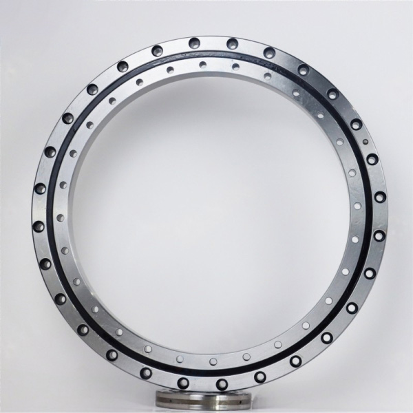
Calculating Slewing Bearing Load Capacity
A slewing bearing must simultaneously handle three types of loads: axial (thrust), radial, and the tilting moment. The tilting moment is often the most demanding and critical load, especially in applications with a large offset or overhung mass, such as a crane boom or excavator arm. The bearing's ability to resist this moment without excessive deflection is what defines its stiffness.
The calculation of a slewing bearing load capacity is not a simple static value. It requires a detailed analysis of the machine's complete duty cycle. You must consider:
Static Load: The maximum load applied when the machine is not rotating. This determines the bearing's basic size and resistance to permanent indentation (brinelling).
Dynamic Load: The loads applied during rotation, which determine the bearing's fatigue life (L10 life). This includes operational forces, acceleration/deceleration, and vibrations.
Load Spectrum: A breakdown of all load cases (magnitude, direction, and duration) that the bearing will experience throughout its operational life. A simple "maximum load" value is insufficient for accurate life calculation.
At BY Bearings, our engineering process is governed by a strict Quality Control system compliant with ISO 9001:2015. We analyze customer-provided load spectrums to recommend a bearing that offers optimal life and performance without costly oversizing. The use of premium GCr15 (SAE 52100) bearing steel, verified for purity, ensures our calculated capacities are met in real-world conditions.
Common Selection Mistakes and How to Avoid Them
Choosing the wrong type of slewing ring bearing can lead to catastrophic failure. Based on our work with over 500 B2B customers in 65+ countries, we have identified several recurring mistakes in the specification process. Avoiding them can save significant time and money.
Mistake 1: Focusing Only on Static Axial Load.
Engineers sometimes select a bearing based solely on the vertical weight it must support. They neglect the tilting moment, which is often the most destructive force. An excavator bucket digging into the ground creates a massive moment load that can pry the bearing rings apart.
Solution: Always calculate the maximum tilting moment. Provide your supplier with a complete load diagram showing all forces and their application points.Mistake 2: Ignoring Rotational Speed and Duty Cycle.
A bearing for a continuously rotating radar antenna has very different requirements than one for a slow-moving access platform. High speeds in a roller bearing can cause excessive heat and lubricant breakdown, while a ball bearing might be too flexible for the radar's pointing accuracy.
Solution: Clearly define the required RPM, the percentage of time the bearing will be rotating, and the load conditions during rotation.Mistake 3: Underestimating the Importance of Structural Stiffness.
The bearing is only as rigid as the structure it's mounted to. If the mounting flanges are not flat, level, and sufficiently stiff, they will deform under load, causing uneven load distribution within the bearing and leading to localized raceway damage.
Solution: Ensure your mounting surfaces meet the flatness and rigidity specifications recommended by the bearing manufacturer. Use the correct bolt grade, quantity, and tightening procedure.Mistake 4: Disregarding Environmental Factors.
Operating in a dusty quarry, a saline marine environment, or at extreme temperatures requires specific considerations for sealing, lubrication, and material coatings. Standard seals and grease may not be adequate.
Solution: Specify the full range of operating temperatures, exposure to moisture or contaminants, and any special environmental conditions upfront. This allows for the selection of appropriate seals, lubricants, and potential corrosion-resistant coatings.
Application Guidance: When to Choose Ball vs. Roller
The choice between ball and roller designs should be driven by the specific demands of the application. There is no single "best" type; there is only the most appropriate type for a given set of load conditions, precision requirements, and budget constraints.
When to Specify Ball Slew Bearings
A Four Point Contact Ball Slewing Bearing is often the most economical choice and performs well in applications characterized by:
Moderate Loads: When axial, radial, and moment loads are relatively low and balanced.
Higher Speeds: Applications requiring smoother, faster rotation where extreme stiffness is not the primary concern.
Cost-Sensitivity: For equipment where the performance of a roller bearing is not strictly necessary, a ball bearing offers a reliable and cost-effective solution.
Example Applications: Light-duty construction equipment, truck-mounted cranes, aerial work platforms, industrial turntables, and packaging machinery.
When to Specify Roller Slew Bearings
Roller slew bearings, including crossed roller and three-row roller designs, are essential for applications demanding high load capacity and rigidity. Choose a roller design for:
Heavy Loads: Especially where high tilting moments are the dominant force, such as in large excavators and mobile harbor cranes.
High Stiffness: Applications requiring high positioning accuracy and minimal deflection, like large CNC machine tools, medical imaging equipment (CT scanners), and radar systems.
Shock and Impact Loads: The line contact of rollers provides superior durability in harsh environments where shock loads are common, such as in mining and forestry equipment.
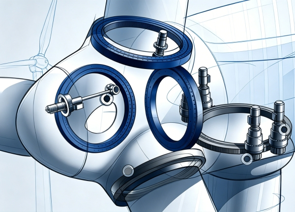
Example Applications: Large hydraulic excavators, wind turbine pitch and yaw systems, tunneling boring machines (TBMs), and other types of Bearings for Construction Machinery Field.
Our commitment to precision is demonstrated in our ability to control runout within 1.5 μm on our high-precision roller bearings. This level of accuracy, verified by 100% pre-shipment inspection, is why customers in demanding sectors like a German semiconductor equipment manufacturer and a Mexican gear grinding machine builder rely on our products.
If your application requires the ultimate combination of compact design and high rigidity, our range of Precision Crossed Roller Bearings may be a more suitable solution than a traditional slewing ring.
For expert guidance on selecting the right bearing for your specific load spectrum and performance targets, get a quote and our engineers will provide a detailed technical review.
 +8618939019135
 sales@bybearings.com
 +8618939019135

