
Verify BRA Series Crossed Roller Bearings Fits First
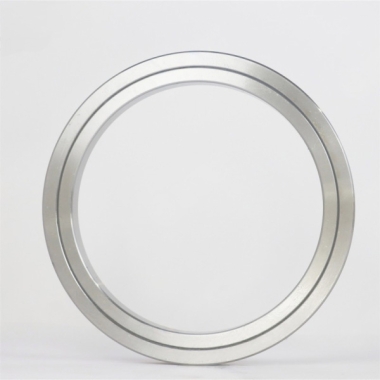
Before you release a housing drawing, one question decides whether the bearing will perform as specified: will the bore, shaft, shoulders and mounting face you have drawn let the ring seat without distorting the raceway? With BRA Series Crossed Roller Bearings, the answer is rarely found in the bearing itself. It sits in your housing geometry. A precision crossed roller bearing can leave the factory with very low runout, then lose that accuracy on a bore that is slightly out of round.
This guide gives you a repeatable fit check to complete on paper and on the first machined part, before you cut the full batch. We do not list BRA dimensions here, because they differ by size. Use the current BRA drawing for the exact values, and use this article to decide which of them to check and in what order.
What to Have on the Desk Before You Check Anything
Some inputs block the whole process. Others can be clarified later. Sort them first so you do not stall on the wrong item.
| Input | Blocks progress? | Why it matters |
|---|---|---|
| Current BRA drawing with ring bore, outside diameter, width, chamfer and mounting hole data | Yes | Every fit and shoulder calculation starts from these values. |
| Which ring rotates (inner or outer) | Yes | The rotating ring and the stationary ring take different fit logic. |
| Accuracy grade required (P5, P4 or P2) | Yes | Tighter grades leave less room for housing form error. |
| Housing and shaft material | Yes | An aluminum housing around a steel ring changes the fit as temperature moves. |
| Load direction and any overturning moment | Can wait | It affects bearing selection more than the fit check. |
| Lubricant choice | Can wait | It can be set once the fit and preload are confirmed. |
Tools: a bore gauge or CMM for diameters, a dial indicator with a magnetic base for runout, a surface plate or CMM for flatness and squareness, and a torque wrench for the clamping bolts.
Fit Verification Workflow for Bore, Shaft, Shoulder and Mounting Surface
Assembly induced runout comes from four places: a bore that is out of round, a shaft seat that is tapered, a shoulder that is not square to the axis, and a mounting face that is not flat. The table connects each one to the check and its failure effect. We have treated BRA Series Crossed Roller Bearings the same way in our own application reviews: geometry first, bolts last.
| Checkpoint | What to verify | Pass signal | If skipped |
|---|---|---|---|
| Housing bore | Diameter, roundness and cylindricity, measured at several heights and at least two angular positions | All readings inside the drawing tolerance; no lobing pattern | Raceway distortion, uneven preload, torque spikes at fixed angles |
| Shaft or inner seat | Diameter and taper along the seat length | No measurable taper; fit matches the intended interference or clearance | Ring creep if too loose, higher friction torque if too tight |
| Shoulders | Height, squareness to the axis and corner radius against the bearing chamfer | Ring face sits fully on the shoulder; the radius clears the chamfer | Ring tilts on the corner, runout appears after bolting |
| Mounting surface | Flatness, perpendicularity to the bore axis and bolt hole position | Flatness and squareness within the drawing values | Ring is pulled out of shape when the bolts are tightened |
| Clamp or retaining ring | Face contact and bolt pattern | Even contact all around; no gap under a feeler gauge | One-sided loading, local wear on the raceway |
Step by step procedure
Pull the exact BRA drawing. Write down bore, outside diameter, width, chamfer and mounting hole pattern. Confirm on the drawing which ring is split or flanged, so the housing and clamp ring match the actual construction.
Assign the fit to each ring. Decide which ring rotates. Use the catalog fit recommendation or ask our engineers. Do not copy a fit from a ball bearing drawing, because crossed roller bearings are preloaded and react to fit differently.
Calculate both tolerance limits. For each mating pair, work out the tightest and loosest condition. If the tightest condition adds interference beyond what the preload and clearance allow, change the tolerance now, not after machining.
Check shoulders on the drawing. The shoulder must support the ring face without touching the cage or seal area, and its corner radius must stay smaller than the bearing chamfer. Squareness to the bore axis belongs on the drawing as a geometric tolerance.
Define the mounting surface. Call out flatness and perpendicularity. Many drawings leave these open, which means the machinist decides.
Add the thermal case. If the housing is not steel, compare expansion at your highest operating temperature. A fit that is correct at 20 °C can loosen or tighten in service.
Machine one housing and measure it. Gauge the bore and seating face on the real part. Compare to the drawing before you release the batch.
Trial mount and measure. Tighten the bolts in a cross pattern in two or three stages, then rotate by hand and measure runout with a dial indicator.
At step 8, a clear success signal is smooth rotation without tight or light spots, and a runout reading close to the bearing's own accuracy. For reference, BY Bearings controls runout within 1.5 μm and inspects every bearing before shipment. A much higher reading after mounting points to the housing or shaft, not the bearing.
Mistakes That Show Up as Runout or Torque Problems
Tolerancing the bore on diameter only. A bore can be in tolerance and still be oval. Add a roundness or cylindricity call-out for precision grades.
Square-cornered shoulders. A sharp inside corner lifts the ring face. It shows up as runout that changes with the bolt torque.
Machining the bore and mounting face in separate setups. Perpendicularity then depends on re-clamping. Machine them in one setup where the part allows it.
Tightening the bolts in a circle. Sequential tightening pushes the ring out of shape in one direction. Use a cross pattern and staged torque.
Treating the fit as unrelated to preload. A tight fit eats the clearance you chose for the bearing, and friction torque climbs. Our team sees this most often in joint and turntable designs where low torque is the goal.
Ignoring a mixed material pair. Aluminum housings with steel rings need a thermal check before the fit is frozen.
Completion Check and Recovery After the Trial Assembly
The task is complete when the assembled bearing turns evenly by hand, the dial indicator reading stays close to the bearing's own accuracy, and the reading does not change after you loosen and retighten the bolts. If any of these fail, go back to the matching step instead of reworking everything.
| Symptom | Most likely cause | Revisit |
|---|---|---|
| Tight spots at fixed angles | Out of round bore or shaft seat | Step 7 (re-measure bore roundness) |
| Runout changes with bolt torque | Mounting face not flat or shoulder not square | Steps 4 and 5 |
| Torque higher than expected, even after repeated measurement | Fit too tight, preload overloaded | Steps 2 and 3 |
| Slight rotation of the stationary ring in service | Fit too loose or clamp contact uneven | Steps 2 and 8 |
| Fit changes between cold start and operating temperature | Material mismatch | Step 6 |
Illustrative example. Suppose a trial mount shows 8 μm runout, and loosening the bolts brings it down to 3 μm. The bearing is not the cause, because the reading moved with the clamping force. The mounting face is the first suspect, so measure its flatness before touching the bore. This is a generic diagnostic path, not a record of a specific customer job.
The same discipline applies to bearings we ship for demanding equipment. BY Bearings has supplied crossed roller bearings for semiconductor equipment in Germany and P2 rotary table bearings for gear grinding in Mexico. In both kinds of work, accuracy depends on seating geometry as much as on the bearing grade. Our quality control process covers the bearing. The housing remains your side of the interface.
Variations That Change the Fit Procedure
Only a few variations alter the steps above. Treat the rest as the same workflow.
Robot joints and harmonic drive modules. Compact housings with thin walls deform more easily, so bore roundness after clamping matters more. See our notes on bearings for industrial robotics.
Rotary tables and turn-mill centers. Larger overturning moments make shoulder squareness and bolt pattern the priority. If your design is closer to a table bearing, compare with rotary table bearings.
Different crossed roller series. Flange and ring constructions differ, so the clamp ring and shoulder design differ too. If the BRA layout does not suit your housing, the BRE Series Crossed Roller Bearings offer another configuration to compare.
Prototype stage. With no minimum order quantity, you can order a small number of bearings to validate the fit on a trial housing before committing to a production run.
Buyer's Checklist Before Releasing the Housing Drawing
Current BRA drawing attached and dimensions copied, not typed from memory
Rotating ring identified and fit class assigned to both rings
Tightest and loosest fit conditions calculated
Roundness, cylindricity, squareness and flatness called out on the drawing
Shoulder corner radius smaller than the bearing chamfer
Thermal check done for any non-steel housing
First article measured and trial mounted before batch release
If you would like a second pair of eyes on the numbers, send your housing and shaft drawings along with the BRA size, accuracy grade and operating conditions, and our engineers will review the fit and shoulder details with you. You can get a quote or ask for selection advice through the contact page.
 +8618939019135
 sales@bybearings.com
 +8618939019135

