
BRA Series Crossed Roller Bearings Load Guide
How can one bearing support radial force, axial thrust, and a tilting moment at the same time without adding separate bearing sets? The answer lies in the crossed roller arrangement. BRA Series Crossed Roller Bearings use rollers arranged at right angles so that different rollers receive force from different directions. This makes the bearing suitable for compact rotary axes, inspection equipment, automation joints, and precision positioning assemblies.
For engineers beginning a housing and shaft design, the key task is not simply checking whether a catalog load rating looks high enough. You need to understand where each force enters the bearing, which roller group carries it, how preload affects stiffness, and whether the mounting structure allows the bearing to use its rated accuracy. For related precision configurations, review Precision Crossed Roller Bearings before selecting a mounting concept.
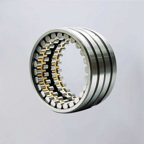
Use the crossed roller arrangement to support three force directions
The direct answer is that a crossed roller bearing distributes radial axial loads and overturning moment loads through alternating rollers positioned at right angles. One set of rollers is oriented to resist force acting in one direction, while the alternate set is oriented to resist force acting in the opposing direction. Because both roller directions are contained in one raceway system, the bearing can carry combined loads within a compact envelope.
This differs from an arrangement using one radial bearing plus two separate thrust bearings. A multi bearing arrangement can work well, but it requires spacing, alignment control, and more components. A crossed roller bearing combines these functions at one bearing position. That can reduce axial stack length and simplify the rotating structure.
| Load type | How force enters the bearing | Practical design effect | Selection limit |
|---|---|---|---|
| Radial load | Force acts perpendicular to the shaft or rotary axis | Controls radial displacement and supports side loading from belts, tooling, or moving masses | Do not assess radial load alone when axial or moment loading occurs simultaneously |
| Axial load | Force acts parallel to the shaft or rotary axis | Controls vertical thrust and directional push pull forces | Load direction, preload, and mounting rigidity can change actual behavior |
| Overturning moment | Force acts at a distance from the bearing centerline | Controls platform tilt, tool deflection, and positioning stability | The applied force arm and housing stiffness must be included in the calculation |
| Combined loading | Radial, axial, and moment forces act at the same time | Reflects real operating conditions in rotary tables and robotic joints | Requires load rating verification using the manufacturer’s applicable method |
The most useful conclusion is simple: select the bearing against the actual load combination, not against the largest isolated load. This approach fits a rotary axis carrying an offset fixture, a robot joint supporting an end effector, or a direct drive turntable with changing process forces. It does not apply as a substitute for checking speed, lubrication, mounting accuracy, contamination, and thermal conditions.
Map the load path through the crossed rollers
A load path map helps prevent a common design error: treating the bearing as if radial, axial, and overturning loads use independent capacity. In practice, they share the same internal contact system. When several loads occur together, the most heavily loaded rollers see the combined effect.
| Applied force | Load path through the assembly | What the crossed rollers do | What can change the result |
|---|---|---|---|
| Radial force | Moving ring → raceway contact → loaded roller group → opposite raceway → fixed ring → housing | Rollers transmit side force across the raceways while limiting radial movement | Housing bore geometry, shaft fit, local deformation, and uneven mounting support |
| Axial force | Moving ring face direction → raceway contact → alternate roller group → opposite ring → mounting face | Rollers oriented in the opposing direction react thrust from either axial direction | Mounting face flatness, bolt tightening sequence, preload, and thermal growth |
| Overturning moment | Offset load → rotating table or arm → bearing ring → concentrated roller zones → fixed ring → housing structure | Opposite sides of the bearing react the tilt through increased load on one zone and reduced load on another | Distance from load to bearing center, ring support, bolt pattern, and base stiffness |
| Combined force | All force paths enter the same ring system at once | The roller load distribution becomes uneven, with some rollers carrying more than others | Actual duty cycle, force direction changes, shock events, and mounting error |
Overturning moment deserves special attention. A centered axial force may produce little tilt demand. Move that same force away from the bearing centerline, and it creates a moment because the force now acts through a lever arm. The bearing may still carry the axial force, yet stiffness and service life can be governed by the added moment.
For example, consider a compact rotary platform with a fixture mounted to one side. Fixture weight creates axial loading, but its offset also creates overturning moment loads. During indexing, acceleration can add radial force. The correct input is therefore not “fixture weight” alone. It is the full force set, the direction of each force, the distance from the bearing centerline, and the operating sequence.
This map is most relevant where positioning error matters, such as CNC axes, inspection tables, semiconductor handling equipment, and robotics. It is less decisive for a lightly loaded mechanism with a centrally supported load and low accuracy requirements, although correct mounting remains necessary in every case.
Interpret combined load capacity instead of comparing isolated ratings
Combined load capacity is not normally the sum of radial, axial, and moment ratings. Ratings are developed for defined conditions, while real machines may apply all three forces together. A bearing that appears suitable under a radial check can become unsuitable once an offset load raises roller contact load on one side of the ring.
Use this selection sequence during early precision bearing design:
Define the load coordinate system. Identify radial directions, axial directions, and the rotation center. This avoids mixing forces referenced to different points.
List static and dynamic loads. Include component mass, process force, drive force, acceleration, deceleration, cable drag, and any externally applied tooling load.
Calculate each overturning moment. Multiply each applicable force by its perpendicular distance from the bearing centerline. Use the actual load arm, not the overall machine length.
Identify the worst duty position. The highest radial load may occur in one position, while the highest moment may occur in another. Check the condition that produces the most demanding combined case.
Confirm preload and stiffness needs. Decide whether low clearance, controlled preload, or another internal condition is needed for positioning stability.
Submit the bearing envelope and load set for review. Include mounting drawings, speeds, duty cycle, accuracy target, and environmental conditions.
The conclusion is that load rating verification must be linked to the real duty cycle. This fits designs with reversing motion, intermittent indexing, cutting force, or an arm mounted off center. It does not mean every low speed design requires the same preload or accuracy grade. Higher preload can improve rigidity and reduce wobble, but it can also increase friction torque and heat generation. The required balance depends on motion quality, speed, load variation, and thermal limits.
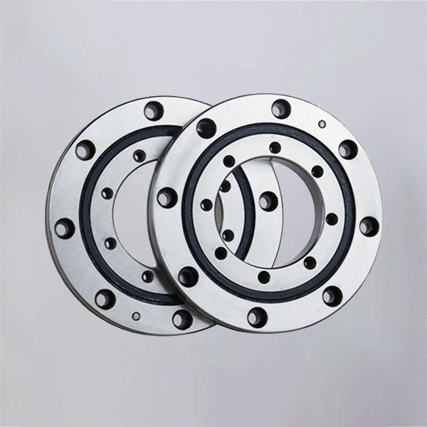
Match preload and mounting surface accuracy to the required stiffness
Bearing preload is the internal load condition established before external service loads are applied. In a crossed roller bearing, suitable preload can reduce internal clearance and improve resistance to small displacement under reversing force. This is useful for a positioning axis that must avoid lost motion when direction changes.
However, preload is not automatically better when it is higher. More preload can increase friction torque, heat, and sensitivity to mounting distortion. A lightly loaded inspection axis may need smooth motion and low torque more than maximum stiffness. A milling table or rotary fixture may place greater value on tilt resistance. The required preload condition should follow the application objective.
Choose controlled preload when reversing accuracy, vibration control, and angular stiffness are the main requirements. This suits compact robotic joints and precision indexing mechanisms. It may not suit applications where low running torque has priority.
Prioritize mounting surface accuracy when the bearing supports a high moment load or must maintain low runout. A distorted housing can create uneven roller loading even when the bearing itself is accurate.
Use rigid ring support when the rotating member carries an offset fixture or process tool. Unsupported areas can allow the ring to flex, reducing the benefit of the bearing’s internal geometry.
Control bolt tightening sequence when installing precision rings. Uneven tightening can alter seating conditions and introduce distortion into the raceway system.
Mounting surface accuracy affects load sharing directly. If the shaft shoulder, housing bore, or mounting face is not properly prepared, the ring can deform after installation. That deformation may concentrate force on a smaller roller zone. The outcome can be higher friction, reduced smoothness, or lower effective service capability under combined loading.
BY Bearings supports crossed roller bearings, harmonic drive bearings, crossed tapered roller bearings, rotary table bearings, slew bearings, thin section bearings, spherical roller bearings, cylindrical roller bearings, and thrust bearings. For axes where a dedicated table bearing structure is a better fit, compare BRT Rotary Table Bearings with the mounting and load arrangement under consideration.
Verify the design inputs that change the bearing decision
A frequent misunderstanding is assuming that “radial, axial, and moment capacity” means each value can be used at its maximum at the same time. That interpretation can lead to an optimistic selection. The correct reading is that the bearing can react force in all three directions, while the allowable combination depends on the actual bearing size, internal specification, load direction, and operating condition.
Before releasing a detailed housing drawing, prepare the following buyer and engineering checklist:
Nominal shaft diameter, housing diameter, and available axial space
Radial load magnitude and direction through the operating cycle
Axial load magnitude and whether thrust reverses direction
Overturning moment loads and their lever arms
Rotation speed, oscillating angle, acceleration, and duty cycle
Required radial runout, axial runout, tilt control, and friction torque behavior
Mounting face details, bolt locations, support wall thickness, and ring clamping method
Lubrication method, contamination exposure, temperature range, and maintenance access
Required preload condition and allowable starting torque
This information allows a supplier to provide useful load rating verification rather than only quoting a nominal size. It also helps determine whether a compact crossed roller design, a crossed tapered configuration, or a dedicated rotary table bearing better matches the machine. For applications with high tilting demand and a different structural layout, see Crossed Tapered Roller Bearings.
BY Bearings has more than 15 years of precision bearing manufacturing experience and supports OEM and ODM customization for special dimensions and mounting requirements. Our grinding accuracy reaches P2 class, with runout controlled within 1.5 μm, subject to the applicable product specification and inspection requirement. We also perform 100% inspection before shipment. These controls matter when a design depends on low runout and consistent mounting behavior rather than load capacity alone.
Apply the load path to a rotary positioning example
Consider an engineering team developing a small rotary fixture for gear inspection. The workpiece mass applies axial load. The fixture is offset from the centerline, creating a moment. During indexing, motor acceleration produces radial loading. If the team checks only workpiece weight, the selection ignores the moment generated by the offset center of gravity and the radial load generated during motion.
For this type of application, begin by placing the bearing centerline on the assembly drawing. Then show the workpiece center of gravity, tooling contact point, motor drive force, and cable routing force. Calculate each moment around the bearing centerline. Next, identify whether the maximum cutting or inspection force occurs at the same time as acceleration. If it does not, check both load cases separately and also review transition conditions.
A useful real reference is BY Bearings’ Mexico customer case involving P2 rotary table bearings for gear grinding. The case illustrates why accuracy level, runout, mounting design, and process loading must be reviewed as one system. It should not be treated as a universal result for every gear processing machine, because fixture geometry, process force, speed, and thermal conditions can differ.
Where the design needs a compact bearing around a hollow shaft or cable path, consider the internal space requirement early. Where a large table must resist process moments, the bearing cross section and base structure may become more important than reducing envelope size. For machine tool layouts, Bearings for Machine Tools can help frame the application discussion.
Submit your load table, mounting drawing, and accuracy target to get a quote and request selection advice for your BRA bearing design.
 +8618939019135
 sales@bybearings.com
 +8618939019135

