
How Precision Crossed Roller Bearings Handle Combined Loads
How Precision Crossed Roller Bearings Handle Combined Loads
Engineers designing a rotary stage often ask the same question: how can one thin bearing row replace two angular contact pairs and still hold tight runout under a tipping moment? The answer sits in the roller geometry itself. Precision Crossed Roller Bearings use alternating rollers set at 90 degrees to each other, each riding on a V-shaped raceway groove, so a single row does the work that normally requires stacked bearing sets. That single fact changes how you size shafts, housings, and preload for an entire motion system — and it's worth understanding before you pick a series.
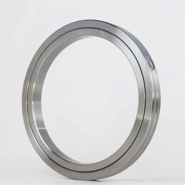
How the Crossed Roller Arrangement Carries Radial, Axial, and Moment Loads Together
Picture two rollers sitting next to each other inside the raceway. One roller's axis points one way, the next roller's axis sits perpendicular to it. Because each roller contacts the V-groove at 45 degrees, every roller can push back against load coming from the radial direction, the axial direction, or a tilting moment — depending on which way the load vector points relative to that roller's axis. Across the full circle, half the rollers resist load from one direction and half resist from the other, so the bearing balances itself without needing a mating bearing on the other side of the shaft.
This is different from a standard ball bearing, which mainly resists load perpendicular to its contact angle and needs a partner bearing (or a separate thrust bearing) to close out the other load paths. It's also different from a four-point contact ball bearing, which handles combined radial-axial loads reasonably well but has a smaller contact footprint and lower moment stiffness per unit of cross-section.
| Load Type | How Crossed Rollers Resist It | What Happens With Undersized Rollers |
|---|---|---|
| Radial | Half the rollers (axis parallel to shaft) take radial push directly through line contact | Shaft deflection increases, affecting concentricity of rotating tool or sensor |
| Axial | The other half of rollers (axis perpendicular) resist thrust in either direction | Axial play opens up, causing positioning drift under cutting force |
| Overturning Moment | Rollers on opposite sides of the circle act as a force couple, resisting tilt like two widely spaced bearings | Angular wobble appears at the load end, worst case for cantilevered robot arms |
That force-couple effect is why a single Precision Crossed Roller Bearing can replace a pair of angular contact bearings mounted back-to-back, while taking up roughly half the axial space. For robot wrist joints and rotary tables, that space saving is often the real reason designers switch architectures — not just the load capacity itself.
Key Parameters That Decide Load Capacity in Practice
Knowing the load path matters less than getting the numbers right. Four parameters determine whether a crossed roller bearing performs as expected once it's installed.
Preload / internal clearance. Crossed roller bearings are usually supplied with slight negative clearance (preload) rather than positive clearance. Preload removes the tiny gap between roller and raceway, which is what controls stiffness and runout. Too little preload and the bearing wobbles under reversing load — a real problem in gear grinding or pick-and-place cycles. Too much preload raises friction torque and heat, which shortens grease life and can cause thermal growth that locks the bearing up at higher speed.
Roller diameter and length-to-diameter ratio. Larger rollers carry more load per contact but raise cross-section height, which fights against the "thin" design goal. A ratio that's too long for the application increases edge stress at the roller ends, a common cause of early raceway spalling under moment-heavy loads.
Mounting surface flatness and squareness. Crossed roller bearings are thin by design, so they flex to match whatever they're bolted to. A housing or shaft that's out of flat by even a few microns will distort the raceway and cancel out a P4 or P2 accuracy grade on paper. This is the single most common field failure we see traced back to installation rather than the bearing itself.
Runout tolerance. Our production line controls runout within 1.5 μm with 100% inspection before shipment, which matters directly for repeat positioning accuracy in semiconductor handling or optical inspection stages. A bearing rated at 1.5 μm runout but installed on a housing with 10 μm of flatness error will still underperform — the two numbers have to match.
If your application involves high tilting moment with cutting vibration, such as a turn-mill spindle or multi-axis rotary table, it's worth reviewing the preload class and runout spec together rather than treating them as separate checkboxes on a datasheet.
Crossed Roller Bearings Versus Other Architectures
Not every application needs a crossed roller bearing. The table below compares the common options engineers weigh during early design.
| Architecture | Radial Capacity | Axial Capacity | Moment Stiffness | Axial Space | Best Fit |
|---|---|---|---|---|---|
| Crossed Roller Bearing | High | High (both directions) | High | Compact, single row | Robot joints, rotary tables, harmonic drive output stages |
| Four Point Contact Ball | Medium | Medium (both directions) | Medium | Compact | Lighter moment loads, lower cost slew applications |
| Paired Angular Contact Ball | High | High (one direction per row) | Medium-High | Wide (needs two bearings) | High speed spindles, lower moment demand |
| Crossed Tapered Roller Bearing | Very High | Very High | Very High | Moderate | Heavy cutting loads, gear grinding tables |
Where loads get heavier and the overturning moment dominates — think gear grinding tables or large CNC rotary tables — Crossed Tapered Roller Bearings often outperform standard crossed rollers because the tapered line contact spreads load over a larger area. We supplied P2-grade rotary table bearings for a gear grinding application in Mexico on this exact reasoning: the moment load and cutting-induced vibration ruled out a lighter four-point contact design.
Common Mistakes When Specifying Crossed Roller Bearings
Sizing for radial load only. Datasheet radial ratings don't tell you how the bearing behaves under combined loading. Always check the combined load formula or ask the supplier to verify against your actual load case.
Ignoring housing stiffness. A thin-section crossed roller bearing bolted into a flexible housing will distort under load even if the bearing itself is within tolerance. Housing wall thickness and bolt pattern matter as much as the bearing spec.
Skipping preload verification after assembly. Preload set at the factory can shift during mounting if bolts are torqued unevenly. A quick runout check after final assembly catches this before it becomes a field complaint.
Choosing standard clearance for high-precision rotary stages. Standard clearance is fine for slow-speed, low-accuracy applications, but semiconductor and medical imaging stages typically need the tighter negative-clearance classes to hold sub-2 μm runout.
Underestimating lead time for custom mounting dimensions. Non-standard bolt circles or special bore sizes take longer to tool up. Flagging this early avoids schedule surprises.
Matching a Bearing Series to Your Load Scenario
Use this checklist before shortlisting a series:
List your actual radial, axial, and moment loads at the bearing location — not just the motor or actuator rating.
Check your allowed axial envelope. If space is genuinely tight, a crossed roller bearing from the BXU Series Crossed Roller Bearings or BRE Series Crossed Roller Bearings line is worth comparing against a paired bearing setup.
If the table or arm sees heavy cutting forces and combined overturning moment, look at BRT Rotary Table Bearings or crossed tapered options before defaulting to standard crossed rollers.
Confirm the runout spec against your positioning tolerance, not just the "precision class" label on the page.
Ask about MOQ and lead time early — flexible MOQ and a 3-6 week custom turnaround are common differentiators between suppliers when your mounting holes aren't standard.
For robot wrist and joint designs specifically, backlash and deadweight droop are usually the deciding factors, which is why harmonic drive output stages and robotics joints lean on the same crossed roller principle covered above — see our notes on Bearings for Industrial Robotics for load cases specific to that application.
A Worked Example: Rotary Table Under Combined Load
Take a 400 mm rotary table carrying a 150 kg fixture offset 200 mm from the bearing centerline. That offset turns a simple vertical load into a real overturning moment — roughly 300 Nm just from the deadweight, before cutting forces are added. A standard four-point contact slewing ring sized only for the vertical load would show measurable tilt at the fixture edge once that moment is applied. Specifying a crossed roller or crossed tapered bearing rated for the combined moment load, with preload matched to the expected cutting vibration, keeps runout inside spec through the full duty cycle. This is the kind of calculation worth running before committing to a bearing family, not after a prototype fails inspection.
Where Quality Control Fits Into Load Performance
A bearing's rated load capacity only holds up if the steel, heat treatment, and grinding are consistent batch to batch. GCr15 bearing steel verified by spectrographic analysis, metallographic checks confirming HRC 60-64 hardness after heat treatment, and 100% runout inspection before shipment are the steps that keep a stated 1.5 μm runout spec real rather than theoretical. These checks, run under an ISO 9001:2015 quality system, are covered in more detail on our Quality Control page if you want to see how a batch is verified before it ships.
If you're sizing a crossed roller bearing against a known radial, axial, and moment load combination, send us your load case and mounting envelope — our team can confirm whether a standard series fits or whether a custom bore and bolt pattern makes more sense, and quote a sample lead time against our 15,000-set monthly capacity. Get a quote to start the review.
 +8618939019135
 sales@bybearings.com
 +8618939019135

