
How Slew Bearings Carry Combined Loads
How can one rotating bearing support a vertical machine weight, side force from a drive, and a large tilting force at the same time? This is the central question engineers must answer before selecting Slew Bearings for cranes, excavators, welding positioners, wind equipment, automation platforms, and other rotating structures.
A slewing ring is not simply a large diameter bearing. It is a structural connection between a stationary frame and a rotating upper structure. The ring must transfer load through its rolling elements, raceways, mounting bolts, and surrounding support faces. If any part of that load route is misunderstood, a bearing that appears adequate on a catalog page can develop uneven loading, high friction, raceway damage, or excessive tilt in service.
For early design work, the practical task is to identify the actual load combination, establish how force reaches the raceways, and select a bearing arrangement that matches the machine structure. The load ratings alone do not tell the full story.
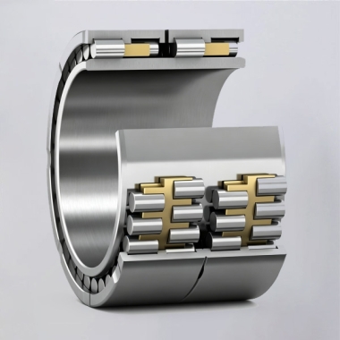
Start with the real forces acting on the rotating structure
Most rotating machines apply three primary force categories to the bearing: axial force, radial force, and overturning moment. These forces often act together. A platform may carry a constant vertical payload, receive side force from a pinion drive, and experience a tilting moment when the payload moves away from the centerline.
The right first step is to draw a free body diagram of the complete rotating assembly. Include the upper structure, payload, actuator forces, gear mesh forces, gravity direction, and locations where loads enter the assembly. Do not begin with bearing size. Begin with force direction and distance from the bearing center.
| Load type | How it enters the bearing | What it affects in practice | Risk if underestimated |
|---|---|---|---|
| Axial load | Vertical payload, machine weight, clamp force, or thrust from an actuator | Rolling element contact on one axial side of the raceway | Localized raceway stress, higher friction, and reduced service life |
| Radial load | Side force from drive systems, wind, process tools, or eccentric motion | Rolling element loading around the radial contact zone | Side movement, uneven contact, and unstable gear engagement |
| Overturning moment | Offset payload, elevated center of gravity, boom force, or tooling force | Opposed raceway zones carry compression and separation forces | Tilt, mounting bolt overload, raceway edge loading, and premature damage |
| Combined loading | Most working positions under operating conditions | Changes the loaded zone and rolling element force distribution | A selection based on one load alone may be unsuitable |
Conclusion: treat the maximum combined condition as the primary selection case, not the largest individual force. This approach fits virtually every rotating machine where payload position or operating direction changes. It does not replace a detailed bearing manufacturer calculation, especially where shock loads, repeated reversals, or unusual mounting flexibility are present.
For example, an elevated arm can create modest radial force but a large overturning moment because the force acts far from the rotational axis. Increasing ring diameter may improve moment resistance, but it may also require a stiffer mounting structure and a different bolt pattern. The bearing, housing, and bolts must be reviewed as one system.
How axial, radial, and overturning moment forces travel through raceways
The load path describes the route force follows from the machine structure into the rings, through rolling elements, across the raceways, and back into the supporting structure. This explanation matters because a bearing does not distribute every force evenly around its full circumference. Only part of the rolling element set may carry the highest load at a given moment.
| Applied force | Raceway action | Rolling element response | Design implication |
|---|---|---|---|
| Axial force | One ring pushes toward the other ring in the axial direction | Balls or rollers transmit compression through their contact points | Check the thrust direction and whether loading can reverse |
| Radial force | The inner and outer rings tend to shift sideways relative to each other | Rolling elements in the side loaded zone accept radial contact force | Confirm that drive force and external side force are both included |
| Overturning moment | One side of the ring closes while the opposite side tends to open | Rolling elements on the compressed side carry greater force; opposite zones may unload | Evaluate bearing capacity, bolt tension, and support face stiffness together |
| Axial and moment combination | Contact force concentrates toward one raceway region | The most heavily loaded elements carry a much larger share of force | Do not add separate ratings without checking the combined rating method |
| Radial and moment combination | Side loading shifts the loaded zone while ring tilt changes contact distribution | Contact can become uneven if mounting faces deflect | Use a ring arrangement suited to the actual direction and duty cycle |
With axial loading, the upper and lower bearing faces transfer force across rolling elements. In a four point contact ball arrangement, the ball contact geometry allows the bearing to accept axial, radial, and moment forces in one compact ring. Under a high moment, however, contact becomes concentrated in opposing regions rather than remaining uniform around the full circle.
Radial force acts differently. It tries to move one ring sideways relative to the other. Gear mesh force is a frequent source. When an external gear or internal gear is driven by a pinion, the gear force should be included in the radial load calculation. Ignoring it can lead to incorrect assumptions about ring position and backlash during operation.
Overturning moment is often the deciding load. It creates a compression side and a separation side. On the compression side, rolling elements and raceways carry higher contact force. On the opposite side, the bearing ring, mounting bolts, and support structure resist opening. If the support face is not sufficiently flat or rigid, the rings can distort and force may concentrate on fewer rolling elements.
Conclusion: a high moment application should be evaluated as a bearing and mounting system. This is especially relevant for booms, cantilevered fixtures, tilting tables, and tall equipment with an offset center of gravity. It is less dominant for compact, centrally loaded turntables, although radial and axial loads must still be verified.
BY Bearings applies 100% inspection before shipment under its ISO 9001 quality system. For applications requiring close rotational control, our manufacturing capability includes grinding accuracy up to P2 class and runout control within 1.5 μm. These production controls support precision bearing work, but machine level tilt and positioning performance still depend on correct mounting surfaces and structural design.
Choose the bearing arrangement around the dominant load path
The bearing type should follow the load combination, required rotation behavior, available installation space, and required structural stiffness. Selecting the largest ring without considering contact geometry may add cost and size without solving the actual load issue.
| Bearing arrangement | Best fit | Load behavior | Limit or caution |
|---|---|---|---|
| Four point contact ball bearing | Compact equipment with combined loads and moderate operating demands | Handles axial, radial, and moment loading through ball contact geometry | May not be the best choice where extremely high stiffness or heavy moment duty dominates |
| Double row ball bearing | Equipment needing increased axial load support and stable load distribution | Two ball rows share load through separate raceway paths | Requires more space and should still be checked for moment and radial conditions |
| Three row roller bearing | Heavy structures with demanding combined loads | Separate roller rows can be assigned to axial and radial load functions | Installation quality and support rigidity remain essential |
| Crossed roller bearing | High precision rotary axes and compact motion systems | Crossed rollers accept loads in multiple directions with high stiffness | Not automatically the preferred option for every large diameter heavy equipment design |
A Four Point Contact Ball Slewing Bearing is a practical starting point when compactness and combined load capability are needed. It suits many general industrial rotating structures. Its limit is that demanding moment stiffness, shock duty, or heavy load concentration may justify a different arrangement.
A Double Row Ball Slewing Bearing can be considered where axial force is substantial and designers need greater load sharing. This arrangement does not eliminate the need to calculate overturning moment. It simply provides a different rolling element layout.
For high load equipment where radial, axial, and moment forces are all significant, a Three-row Roller Slewing Bearing may provide a more suitable load separation concept. It fits demanding structural applications, but it is not always necessary for lower load equipment with limited installation space.
Where the priority is rotary positioning accuracy rather than large diameter structural support, engineers may also compare Precision Crossed Roller Bearings. Their contact arrangement is suited to compact high stiffness axes, such as automation or precision equipment. The application must still be reviewed for diameter, mounting design, rotational speed, and actual external loads.
Check mounting faces and bolts before approving bearing size
A correctly selected ring can still fail early when it is mounted on weak, uneven, or distorted support faces. The support structure must transfer force into the bearing ring without local gaps. Under moment loading, a flexible flange can bend, changing raceway contact and increasing load on selected rolling elements.
Use the following design review procedure before issuing a bearing request or releasing a drawing.
Identify every load source. Include payload, self weight, actuator forces, gear mesh forces, wind forces where relevant, and process forces.
Define each load direction. Record whether axial force acts in one direction only or can reverse during operation.
Calculate the offset distance. Measure the perpendicular distance from each force line to the bearing center to determine its moment contribution.
Identify operating positions. Check transport, startup, working, emergency stop, and maximum reach conditions rather than one nominal position.
Review support faces. Confirm that the housing or frame offers continuous support close to the raceway region.
Review bolt loading. Moment loads can increase bolt tension on the opening side, so bolt selection must be considered with bearing capacity.
Confirm gear force. If the ring includes gear teeth, include the drive force and check alignment between pinion and ring.
Submit the duty details. Provide load cases, mounting drawings, rotation requirements, and environmental conditions for supplier review.
Conclusion: approve the bearing only after confirming the ring, bolts, and support faces work together under the governing load case. This procedure is appropriate for new machine development and redesign projects. It does not substitute for finite element analysis when the surrounding frame has thin sections, long cantilevers, or complex welded geometry.
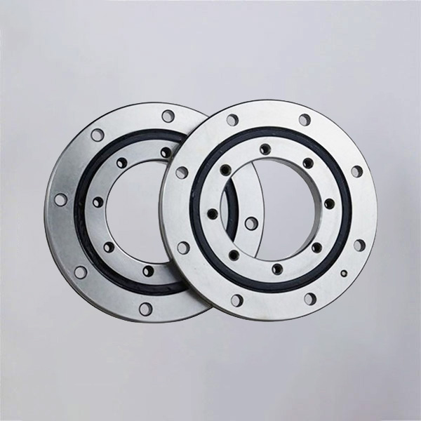
Avoid selection errors that distort the load path
The most frequent bearing errors are not always caused by an incorrect catalog part number. They often begin with incomplete load input or assumptions about mounting stiffness.
Checking only vertical load: This misses the effect of side force and overturning moment. Use a combined load case instead.
Ignoring the center of gravity: A load located away from the axis generates moment even when its weight is unchanged. Calculate the offset for every major operating position.
Using nominal gear force only: Acceleration, direction reversal, and process resistance can alter radial loading. Include the actual operating condition supplied by the drive and machine design team.
Assuming the ring corrects structural deflection: A bearing cannot compensate for flexible flanges. Improve the support design if local deformation is expected.
Selecting by outside diameter alone: Diameter affects moment leverage, but raceway design, rolling element arrangement, mounting bolts, and duty cycle also matter.
Forgetting reversed loading: Tilting machines and moving booms may reverse axial or moment direction. State this clearly during selection.
Requesting a rating without a duty description: A supplier needs load direction, speed, rotation angle, frequency, mounting layout, and environment to make a useful recommendation.
BY Bearings supports OEM and ODM customization, including flexible customization for special dimensions and mounting requirements. Our 13,500 m² intelligent factory includes a CNC workshop and automated heat treatment line, with monthly production capacity of 15,000 sets. Those resources help support industrial sourcing requirements, but the final design still needs application specific load data and drawings.
Use a practical data package for early bearing selection
Early selection is faster when the engineering team sends a defined set of inputs rather than only an outside diameter request. A usable package lets the supplier assess whether the required ring can carry the actual axial load capacity, radial load capacity, and overturning moment load in the intended arrangement.
| Information to provide | Why it matters | What happens if omitted |
|---|---|---|
| Maximum axial force | Defines thrust demand and load direction | The bearing may be checked against the wrong raceway condition |
| Maximum radial force | Shows side loading from process and drive forces | Ring movement and gear alignment risk may be missed |
| Maximum overturning moment | Shows the tendency of the structure to tilt | Raceway concentration and bolt loading may be underestimated |
| Mounting drawings | Shows ring support, bolt layout, and available space | Interference or insufficient structural support may appear late |
| Rotation speed and duty cycle | Helps assess friction, lubrication, and operating behavior | The recommendation may not fit the actual motion pattern |
| Environmental conditions | Guides sealing and lubrication considerations | Contamination or temperature concerns may be overlooked |
For general industrial designs, review the available Slew Bearings range alongside the application load data. For precision indexing tables and machine tool rotary axes, Rotary Table Bearings may be more appropriate where accuracy and tilting stiffness are central requirements.
BY Bearings has more than 15 years of precision bearing manufacturing experience and exports to 65+ countries while serving 500+ B2B customers. For a suitable recommendation, submit your load cases and mounting drawing to get a quote.
 +8618939019135
 sales@bybearings.com
 +8618939019135

