
Prevent Gear Wear When Installing Slew Bearings
Why does a ring gear that looked perfect on the bench show polished, one-sided tooth wear after a few hundred hours? The gear steel is rarely the cause. In most failure reviews, the problem is how the Slew Bearings were seated, bolted and meshed with the pinion. This article gives maintenance teams and machine builders a diagnosis order: what to check first, what each symptom points to, and when a check does not apply.
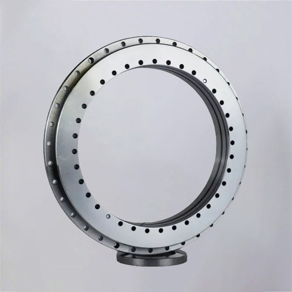
Why Ring Gear Wear Usually Starts at Installation
A slewing ring is only as flat as the structure it sits on. Bolted to a warped surface, the ring takes on that warp. The raceway and the gear teeth move with it, so the pitch circle is no longer round. The pinion then meets a different tooth geometry at every angle, and the load concentrates on a few teeth.
That is why installation-related wear is localized. It shows up at one angular position, on one end of the tooth, or on one flank. Wear from lubrication problems or general overload is usually spread more evenly around the ring.
Keep one limit in mind. Everything below assumes the gear teeth were cut correctly and the grease is the right type. If the lubricant is wrong or contaminated, fix that first, because installation checks will not cure it.
Diagnosis Order: Flatness, Bolt Preload, Pinion Alignment, Backlash
These four factors interact, so check them in a fixed order. Earlier items change the readings of later ones. Adjusting backlash on a ring that sits on a warped face only hides the problem at one position.
| Check order | What to check | Symptom it explains | Judgment criterion |
|---|---|---|---|
| 1. Mounting flatness | Mounting faces of the supporting structure and the ring, with a dial indicator or feeler gauge before the bolts go in | Wear at the same angular position every revolution; turning torque that rises and falls once per turn; tooth contact that shifts around the ring | Compare readings with the flatness requirement on your drawing or the bearing manufacturer's data. If the gap or deviation exceeds it, correct the structure. Do not close the gap with bolt force. |
| 2. Bolt preload | Torque of every bolt, in the specified sequence, with a calibrated wrench | Reddish fretting dust at the joint faces; bolts that loosen; wear clustered near certain bolts | All bolts should reach the same specified preload. Uneven torque distorts the ring, the same way a warped face does. |
| 3. Pinion alignment | Tooth contact pattern, checked with marking compound, across the full tooth width | Contact or pitting at one end of the tooth; polish on one edge of the flank | The pattern should sit centered on the flank and cover most of the tooth width. A one-ended pattern means the pinion shaft is skewed or the ring is tilted. |
| 4. Backlash adjustment | Backlash measured at several points around the ring, especially the tightest point | Too tight: heat, whine, bright polished flanks, rising torque. Too loose: impact marks, pitting near the tooth root, knocking at direction reversal | Set backlash to the gear designer's specification at the tightest point, not the average. Always verify after the bolts are fully tightened. |
How to read the symptoms in this order
Same position, every revolution: start with flatness, then bolt preload. A fixed angular position points to a fixed geometry error.
One end of the tooth worn: suspect pinion alignment first, but confirm flatness. A ring tilted by an uneven face looks exactly like a skewed pinion.
Whole ring polished and warm: backlash is probably too tight, or runout is forcing the pinion deeper into the mesh at some points.
Pitting at the tooth root with impact noise: backlash is too large or the load reverses often. Check backlash, then review the drive's acceleration profile.
When this order does not apply: if the machine ran for years without wear and the damage appeared suddenly, look for a changed condition first. That could be a loose bolt, a cracked support weld or a replaced pinion.
Step-by-Step Installation Procedure That Protects the Gear
Clean and inspect the mounting faces. Remove paint, burrs and rust. Check flatness before the ring touches the structure.
Locate the soft spot. Most slewing rings have a marked unhardened zone on the raceway. Position it away from the main load direction, as the bearing drawing indicates.
Seat the ring without forcing it. Lower it evenly. If you need to hammer or pry it into place, stop and recheck the faces.
Fit the bolts and tighten in a cross pattern, in stages. Raise the torque gradually until every bolt reaches the specified preload, then make one final pass in the same sequence.
Turn the ring by hand. Torque should feel even through the full rotation. Any single tight spot means you should go back to the flatness check.
Mount the pinion and set the mesh. Apply marking compound to the pinion teeth, rotate through the mesh, and read the contact pattern.
Measure backlash at multiple positions. Adjust at the tightest point to your specification, then lock the pinion position.
Re-check after the first operating period. Retorque bolts and re-inspect the contact pattern, since settling can change both.
This procedure fits ring-and-pinion drives on turntables, cranes and similar equipment. For rotary tables with integrated drives, such as Rotary Table Bearings in machine tools, follow the manufacturer's mounting instructions, since the drive arrangement differs.
Common Mistakes That Wear Out the Ring Gear
Using bolt force to pull the ring flat. It looks fine on the day, but the ring stays distorted and the gear wears at the high spots.
Tightening bolts in circular order. This pushes the ring out of round. Use a cross pattern.
Setting backlash with the pinion at the loosest point. The mesh then binds at the tightest point once the machine runs.
Checking tooth contact before final bolt torque. Tightening changes the ring's shape and moves the pattern.
Ignoring the soft spot. It is a raceway issue, but it changes how the ring deflects under load and affects the mesh over time.
Reusing damaged or stretched bolts. Preload will not hold, and the joint relaxes unevenly.
Worked Example: Reading a Wear Pattern on a Turntable
The following is an illustrative scenario, not a customer case. A turntable shows bright polish on a single flank, concentrated over roughly one quarter of the circumference. The pinion looks fine.
Flatness first. Measure the support face at four positions. One quadrant sits low. That matches the worn quarter.
Bolt preload second. Bolts in the low quadrant show fretting dust, which means they were pulling the ring down into the gap.
Pinion alignment third. The contact pattern is skewed toward one end of the tooth in the same quadrant, which fits a tilted ring rather than a skewed pinion.
Corrective action. Shim or re-machine the low area, retighten in sequence, then reset backlash. Adjusting the pinion alone would have moved the wear to another place.
Choosing the Bearing So Installation Is Easier
Some installation problems are easier to avoid at selection. A stiffer ring section tolerates small flatness errors better than a thin section, but it does not remove the need for a flat face. The bearing type also changes how the load reaches the gear.
| Bearing type | Suits | Limit |
|---|---|---|
| Four Point Contact Ball Slewing Bearing | Moderate combined loads with compact height | Less stiffness than roller types under heavy overturning moments |
| Double Row Ball Slewing Bearing | Higher axial and moment capacity than single row | Needs a flatter, stiffer mounting structure |
| Three-row Roller Slewing Bearing | Heavy loads such as construction and wind equipment | The largest structure, so installation preparation matters most |
Before ordering, confirm these points:
Gear type and position: internal or external teeth, and whether they are hardened.
Pinion specification and module, so backlash can be set to the drive designer's value.
Mounting structure stiffness and the flatness you can actually achieve on site.
Soft spot location relative to the main load.
What BY Bearings Can Support
BY Bearings has more than 15 years of precision bearing manufacturing experience. Our 13,500 m² intelligent factory has a CNC workshop and an automated heat treatment line, and every bearing goes through 100% inspection before shipment under an ISO 9001 quality system. Our products carry CE, RoHS and TUV certification. Details of the inspection process are on our Quality Control page.
On the precision side, we have supplied P2 rotary table bearings for gear grinding in Mexico, where runout and mounting accuracy matter just as much. OEM and ODM customization is available, including special dimensions and mounting holes, and there is no minimum order quantity. Standard products carry a 12-month warranty from the date of shipment. Our broader range, including Slew Bearings, is listed under Precision Bearing Solutions.
If you are writing an installation procedure or investigating a worn ring gear, send us your drawings, the wear pattern photos and the mounting details. Our team can give selection and installation advice, or you can get a quote for a replacement.
— Daniel Wei, Precision Bearing Product & Application Manager, BY Bearings
 +8618939019135
 sales@bybearings.com
 +8618939019135

